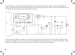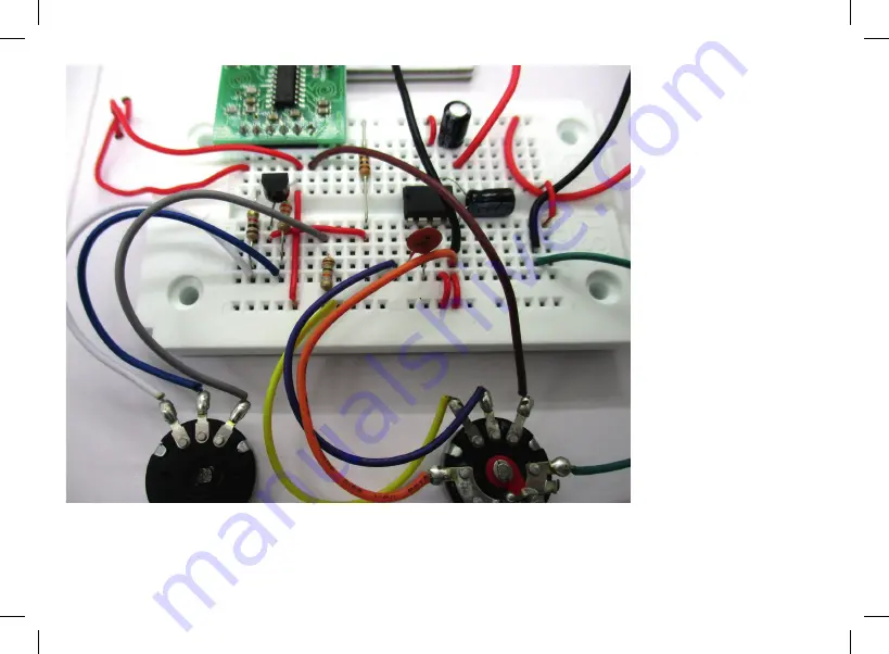
The tuning voltage set at the
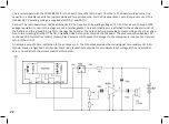
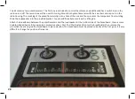
left potentiometer is applied
via a 220 kΩ resistor (red,
red, yellow) to the reset pin
and thus to the varcap diode.
When the wiper of the poten
-
tiometer is placed near +3 V,
the resulting frequency is
low. Accordingly, a maximum
frequency will result from a
setting of 0 V.
The 220 kΩ resistor increases
the influence of the automat
-
ic frequency control (AFC)
on the tuning process. An
improperly adjusted station
will automatically be tuned
more precisely. While slowly
scanning the FM range, you
will register a certain lock-in
range where the radio clings
to a chosen station. This sim
-
plifies selecting a station.
However, with only one
potentiometer, the tuning
range would be too large and
the FM range would only take up part of the whole scale. Two resistors are used to limit the range to values from 87.5 MHz
to 108 MHz. Now the FM range takes up the whole scale. The 1 kΩ resistor sets the lower frequency limit; the 10 kΩ sets the
upper one.
31
Summary of Contents for RETRO RADIO
Page 1: ......
Page 14: ...14...
Page 15: ...Step 2 Sound Generator Required components 10 k resistor brown black orange 15...
Page 17: ...17...
Page 20: ...20...
Page 24: ...Step 5 Tuning Required components Hook up wire 24...
Page 29: ...29...
Page 35: ...Measured voltages 35...


