Repeat the first radio experiment without a particular tuning.
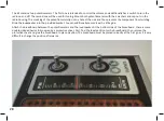
It is sufficient to remove the middle connection of the poten
-
tiometer (blue). When you turn on the radio, it should find a
station, except when there is a problem with the voltage sup
-
ply. Reattach the potentiometer. If it is now impossible to find
a station by means of the potentiometer, the problem resides
in the area of the potentiometers and the attached resistors.
For further troubleshooting, a voltmeter can be useful.
However, with some skill you can also use the amplifier for a
rough voltage check. To do so, pull out the brown potentiom
-
eter connection and use it as measuring wire. Set the volume
potentiometer to the middle position or lower. When you
now touch a point of the circuit with the brown wire, a click-
ing noise occurs. Its volume indicates the voltage. Also test
the full operating voltage (9 V, very loud) and the negative
connection (GND, 0 V, no sound). Further tests should yield
the following results:
•
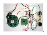
BAT pin of the board: 3 V, loud
•
GND pin of the board: 0 V, no sound
•
NF output of the board: 1.5 V or more, loud
•
Grey wire at the tuning potentiometer: 0.8 V, low noise
•
White wire at the tuning potentiometer: 2.9 V, loud
•
Middle pin of the tuning potentiometer (blue): adjustable
from 0.8 V to 2.9 V, low to loud noise
When you get a significantly different result at one of the
measuring points, the problem probably resides in the re-
spective area. In most cases, it is a contact problem, a wrong
component or an incorrect connection.
In rare cases, one of the components may be faulty. In partic
-
ular the loudspeaker, the amplifier IC and the FM board can
be damaged by applying excessive voltage. Also, the pins of
the loudspeaker and the potentiometers can be damaged.
Contact problems can occur at the potentiometers and the
switch.
34
Summary of Contents for RETRO RADIO
Page 1: ......
Page 14: ...14...
Page 15: ...Step 2 Sound Generator Required components 10 k resistor brown black orange 15...
Page 17: ...17...
Page 20: ...20...
Page 24: ...Step 5 Tuning Required components Hook up wire 24...
Page 29: ...29...
Page 35: ...Measured voltages 35...


