Hardware Reference Manual
SOM
Version 1.0
- 39 -
eInfochips Confidential
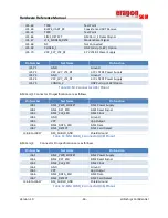
J17.16
CDC_SPEAKER2_OUT_M
Speaker2 Output Negative
Table 6:
Audio Header (J17) Pinout
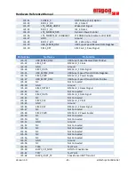
Below is the Pinout Specification of J18,
Pin Number
Net Name
Pin Function
J18.1
CDC_MIC_BIAS3
MIC Bias_3 Voltage
J18.2
CDC_MIC_BIAS4
MIC Bias_4 Voltage
J18.3
GND
Ground
J18.4
GND
Ground
J18.5
CDC_MIC_BIAS1
MIC Bias_1 Voltage
J18.6
CDC_DMIC_CLK1
Digital MIC_1 Clock
J18.7
GND
Ground
J18.8
CDC_DMIC_DATA1
Digital MIC_1 Data
J18.9
CDC_DMIC_CLK0
Digital MIC_0 Clock
J18.10
CDC_DMIC_CLK2
Digital MIC_2 Clock
J18.11
CDC_DMIC_DATA0
Digital MIC_0 Data
J18.12
CDC_DMIC_DATA2
Digital MIC_2 Data
J18.13
CDC_LINE_OUT2_P
Line Output_2 Positive
J18.14
CDC_LINE_OUT1_P
Line Output_1 Positive
J18.15
CDC_LINE_OUT2_M
Line Output_2 Negative
J18.16
CDC_LINE_OUT1_M
Line Output_1 Negative
Table 7:
Audio Header (J18) Pinout
6.3.6
Sensors
ERAGON624 supports multiple sensors as below,
Magnetometer, Accelerometer& Gyrometer, Pressure sensor and ALSP (Ambient Light and
Proximity) sensor interfaced to APQ8053 through BLSP4_I2C Port
Temperature sensor in interfaced to APQ8053 through BLSP6_I2C Port
6.3.7
Micro SD Card
The ERAGON624 carrier card could be connected with Micro SD card interface for external
storage device (SD card). SD card is interfaced with APQ8053 (on SOM) through 4-bit SDC2 data
signals along with SDC2 clock and SDC2 command signals. GPIO_133 of APQ8053 is used to
detect SD card insertion and removal.
Summary of Contents for Eragon 624 SOM
Page 1: ......

