Hardware Reference Manual
SOM
Version 1.0
- 41 -
eInfochips Confidential
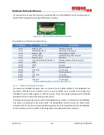
A 3-wire (audio out only) I2S channel is routed directly from the APQ8053 SoC I2S interface pins to
the DSI-HDMI bridge Board through HDMI Audio connector.
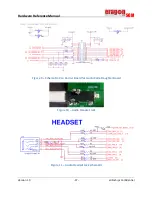
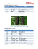
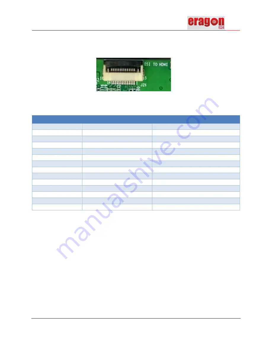
Figure 14 – DSI to HDMI Audio Connector J26
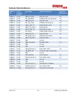
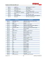
Pin specifications for J26 is mentioned below,
Pin Number
Net Name
Pin Function
J26.1
MI2S_1_D0
I2S Data 0 signal
J26.2
DSI2HDMI_INT_N
HDMI Interrupt Signal
J26.3
MI2S_1_WS
I2S Word Sync Clock l
J26.4
HDMI_HPD_N
HDMI Hot Plug Detect Signal
J26.5
MI2S_1_SCK
I2S Clock
J26.6
CEC_CLK/ PRI_MI2S_MCLK_A
9.6MHz System Clock frequency
J26.7
GND
Ground
J26.8
GND
Ground
J26.9
NC
Not Connected
J26.10
VCC_1V8
1.8V Supply
J26.11
NC
Not Connected
J26.12
VCC_5V0
5V Supply
J26.13
NC
Not Connected
J26.14
VCC_3V3
3.3V Supply
Table 8:
HDMI Audio Connector (J26) Pinout
6.3.9
HDMI to CSI Audio interface
The Qualcomm APQ8053 Processor does not include a built-in HDMI interface. The ERAGON624 has
the built-in MIPI-CSI 4 lanes interface, which is used, as HDMI input. A HDMI to CSI bridge chip
TC358840 converts HDMI signals to MIPI CSI Signals. These CSI signals interfaced with APQ8053
through MIPI CSI connectors mentioned in CSI section.
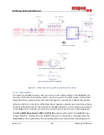
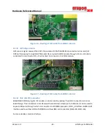
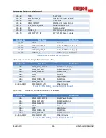
This Bridge Board supports audio as well. The ERAGON624 uses a MI2S_1 interface from the APQ8053
chip which is mentioned in the below block. The ERAGON624 contains the 16 pin HDMI Audio
Connector (J27) on the board. A 6-wire (audio input) I2S channel is routed directly from the APQ8053
SoC I2S interface pins to the HDMI to CSI Bridge Board through HDMI Audio connector.
Summary of Contents for Eragon 624 SOM
Page 1: ......


