Hardware Reference Manual
SOM
Version 1.0
- 42 -
eInfochips Confidential
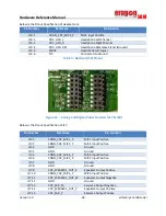
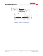
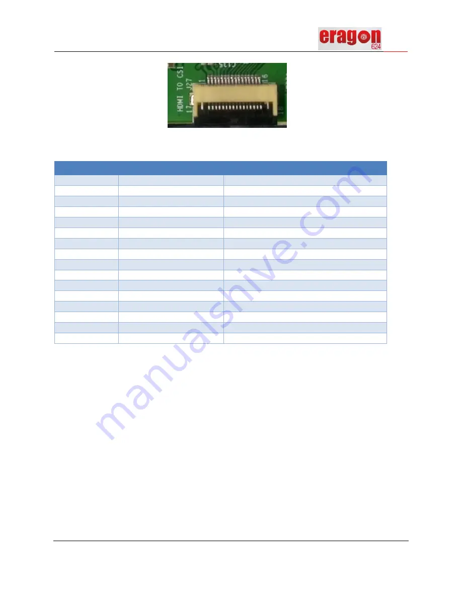
Figure 15 – HDMI to CSI Audio Connector J27
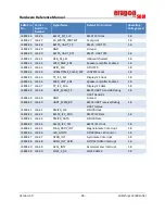
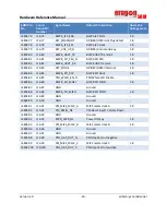
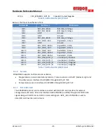
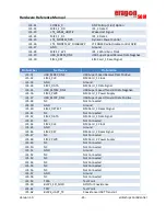
Pin specifications for J27 is mentioned below,
Pin Number
Net Name
Pin Function
J27.1
VCC_3V3
3.3V Supply
J27.2
VCC_3V3
3.3V Supply
J27.3
VREG_L2_1P1
1.2V Supply
J27.4
VCC_1V8
1.8V Supply
J27.5
HDMI_I2C_SDA
HDMI I2C Data
J27.6
HDMI_I2C_SCL
HDMI I2C Clock
J27.7
MI2S_1_SCK
I2S Clock
J27.8
MI2S_1_WS
I2S Word Sync Clock
J27.9
MI2S_1_D3
I2S Data 3 Signal
J27.10
MI2S_1_D2
I2S Data 2 Signal
J27.11
MI2S_1_D1
I2S Data 1 Signal
J27.12
MI2S_1_D0
I2S Data 0 Signal
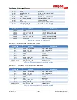
J27.13
HDMI_INT_GPIO
HDMI Interrupt
J27.14
HDMI_RST_N
HDMI Reset
J27.15
GND
Ground
J27.16
GND
Ground
Table 9:
HDMI Audio Connector (J27) Pinout
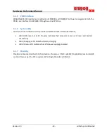
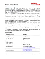
6.3.10
WiFi + BT chip antenna
As mentioned in ERAGON624 SOM blocks, Wi-Fi + BT RF signal routed from SOM to Carrier card
through U.FL-to-U.FL cable connected from connector J8 at SOM and connector J4 at Carrier card. After
that, it is interfaced to Fractus chip antenna FR05-S1-NO-1-004 (ref ANTENNA1) to radiate. During the
design of carrier Board, customer needs to use the same chip Antenna on application Board.
For Placement & routing of the Antenna on Carrier Board, contact eInfochips to get the detailed
information.
Summary of Contents for Eragon 624 SOM
Page 1: ......

