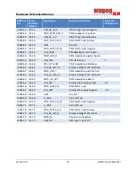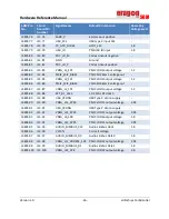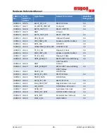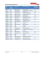
Hardware Reference Manual
SOM
Version 1.0
- 34 -
eInfochips Confidential
Guidelines to Design Carrier Board
6.3.1
Power Supply
ERAGON624 SOM can be powered through 3.8V@4.2A DC input to give power to VBAT pins (as per pin-
outs table between SOM & Carrier).
6.3.2
Boot Configuration
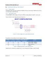
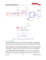
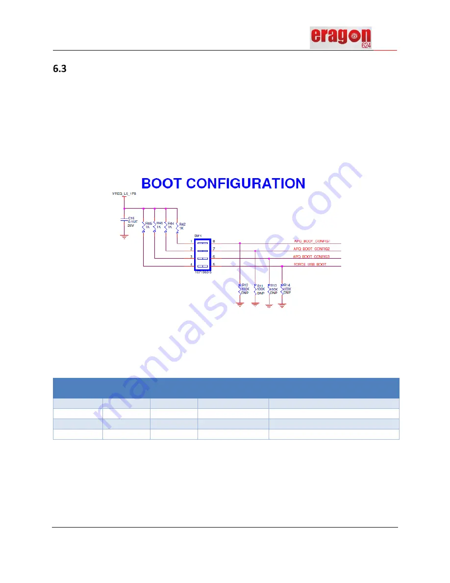
The ERAGON624 can be configured to function in different modes placing the switch on carrier card.
Below schematic can be followed for Boot configuration:
Figure 4 – Boot Configuration Switch (SW1) schematic
Below table mentions different boot configurations options,
CONFIG_1
(Position-1)
CONFIG_2
(Position-2)
CONFIG_3
(Position-3)
FORCE_USB_BOOT
(Position-4)
Function
0
0
0
0
SDC1 -> SDC2 -> USB 3.0
0
1
0
0
SDC2 -> SDC1 -> USB 3.0
0
1
1
0
SDC1 -> USB 3.0
0
0
0
1
USB 3.0
Table 4:
ERAGON 624 BOOT Configuration options
CONFIG switch in ON position indicates level 1. To boot through eMCP make sure switch is 0000.
Summary of Contents for Eragon 624 SOM
Page 1: ......

