GB
- 21 -
Warning!
This equipment generates an electromag-
netic
fi
eld during operation. Under certain
circumstances this
fi
eld may actively or pas-
sively impede medical implants. To reduce
the risk of serious or fatal injuries, we recom-
mend persons with medical implants to con-
sult their doctor and the manufacturer of the
medical implant prior to using the equipment.
5. Before using the equipment
The lawn mower is delivered partly assembled.
The push bar and the side ejector must be
fi
tted
before you use the lawn mower. Follow the ins-
tructions step by step and refer to the pictures
when assembling.
Mounting the push bar (Fig. 2 to 6).
Insert the push bar holder (Fig. 2/Item 3) into the
long handle mount (5) and secure with the faste-
ning screw (Item 11), the washer (Item 11a) and
the fastening nut (Item 10) (Fig. 3/4).
The top push bar (Fig. 2/Item 2) must be pushed
onto the push bar holder and secured with the
fastening screws (Item 11), the fastening nuts
(Item 10) and the washers (Item 11a) as shown
in Fig. 5. Then fasten the cable to the push bar by
the cable clips (Item 13).
The push bar can be adjusted to 3 di
ff
erent height
settings. To adjust the height, undo the fastening
nut (Item 10) and move the bar into the required
latch (Fig. 5/6).
Warning!
Always set the identical handle height on both
sides.
•
Use the cable clips to align the cable with the
long handle (Fig. 6/Item 13).
Adjusting the cutting height
Caution!
Adjust the cutting height only when the machine
has been switched o
ff
, the safety plug (12) has
been pulled out and the batteries (15) removed.
Before you begin to mow, check to ensure that the
blade is not blunt and that none of the fasteners
are damaged. To prevent any imbalance, replace
blunt and/or damaged blades. To carry out this
check,
fi
rst switch o
ff
the motor and pull out the
safety plug.
The cutting height must be adjusted as follows
(see Fig. 7a, 7b):
1. Push the lever of the front cutting height ad-
justment (6) outwards.
2. Set the lever of the front cutting height adjust-
ment to the desired cutting height.
3. Release the lever of the front cutting height
adjustment and check that it is securely sea-
ted in the lock.
4. Repeat the procedure on the lever of the rear
cutting height adjustment (7).
5. For the best cutting results make sure that
the same cutting height is set at both the front
and rear lever.
Side ejector (Fig. 8)
Hook in the side ejector adapter (14) as shown
in Fig. 8.
Important!
The side ejector must not be used when you want
to mow less than 2cm of the grass height in one
pass.
Use the side ejector when you want to mow more
than 2cm of the grass height in one pass.
Charging the battery (Fig. 13)
1. Take the battery pack out of the equipment.
Do this by pressing the pushlock button.
2. Check that your mains voltage is the same as
that marked on the rating plate of the battery
charger. Insert the power plug of the charger
(16) into the socket outlet. The green LED will
then begin to
fl
ash.
3. Insert the battery pack (15) into the battery
charger.
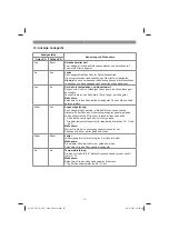
4. In the section entitled „Charger indicator“ you
will
fi
nd a table with an explanation of the LED
indicator on the charger.
The battery pack can become a little warm during
the charging. This is normal.
If the battery pack fails to charge, check:
•
whether there is voltage at the socket outlet
•
whether there is good contact at the charging
contacts.
If the battery pack still fails to charge, send
•
the charging unit
•
and the battery pack
to our customer service center.
Anl_GE_CM_36_48_Li_M-Solo_SPK13.indb 21
26.10.2021 14:04:25

