GB
14
8. Before starting the machine
Unpack the surfacing and thicknessing plane and
examine it for any transit damage.
The machine has to be set up and aligned where
it can stand securely.
All covers and safety devices have to be properly
fitted before the machine is switched on.
It must be possible for the planing knife to run
freely.
When working with wood that has been
processed before, watch out for foreign bodies
such as nails or screws, etc.
Before you press the ON/OFF switch (1), make
sure that the planing knife is fitted correctly and
that the machine’s moving parts run smoothly.
Check that the voltage on the rating plate is the
same as your supply voltage before you connect
the machine to the power supply.
9. Assembly
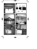
9.1 Parallel stop (Figure 4/5)
Place the knife cover plate (25) on the feed table
(13) as shown in Figure 5.
Place the parallel stop (6) on the feed table (13).
Ensure that the holes in the parallel stop (6) and
the knife cover plate (25) line up with the internal
threads in the feed table (13).
Secure the parallel stop (6) to the feed table (13)
using the two Allen screws supplied.
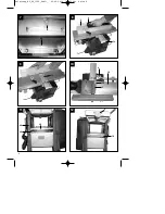
9.2 Planing knife cover (Figure 1-3)
Place the holder for the planing knife cover (8)
on the left-hand side of the planing table (14) so
that the pin and grub screw engage in the two
holes.
Secure the planing knife cover (12) using the
locking knob (33) supplied
9.3 Rubber feet/Tipping guard bar (Figure 1-2)
Secure the four rubber feet (11) to the underside
of the machine using the Allen screws supplied.
Screw the four tipping guard bars (26) into the
internal threads provided and secure them with
the nuts supplied.
10. Operation
Important:
The surfacing and thicknessing plane
has been specially designed for planing solid wood.
High alloy knives (21) are used for this purpose. The
contact surface of the workpiece must be flat for
thicknessing. If you wish to plane large or heavy
workpieces, the machine must be secured in place
(for example using screw clamps).
The ON/OFF switch (1) is on the left-hand side of
the machine under the yellow hinged cover.
Press the green key “I” to switch on the machine.
Press the red key “0” to switch off the machine.
The machine is fitted with an overload switch
(35) to protect the motor. In the event of an
overload, the machine will cut out automatically.
After a short time, the overload switch (35) can
be reset again.
11. Surfacing
11.1 Adjustment (Fig. 1/3/4)
Turn the adjustment knob for cutting depth (11)
to set the height of the feed table (13). The set
cutting depth can be read off the scale (18).
Loosen the parallel stop (6) with the clamp lever
(7). Set the required angle. The set angle can be
read off the scale (19). Secure the parallel stop
(6) with the clamp lever (7) again after making
the setting.
11.2 Fitting the chip extractor (Figure 6/7/14/17)
Fit the hand crank (4) to the post on the planing
table (14). Turn the hand crank (4) counter-
clockwise to move the thicknessing table (20) to
its lowest position.
Place the chip extractor (5) on the thicknessing
table (20). Ensure that the three stop journals on
the chip extractor (5) engage in the three holes
on the thicknessing table (20).
Turn the crank handle (4) clockwise until the chip
extractor (5) is firmly secure and the recess (b) is
on the safety switch (d). Secure the chip extractor
(5) on the thicknessing table (20) using the nut
supplied (a), as shown in Figure 7.
Fit the 100 mm chip extractor adapter (27) and, if
necessary, the 35 mm chip extractor adapter
(28) to the chip extractor (5).
Connect the plane to a chip extraction system
(not supplied).
Raise the planing knife cover (12).
11.3 Surfacing mode (Figure 1/8/9)
Connect the mains plug to the mains lead. Open
the yellow cover (1) and press the green button
“I” to start the plane.
Place the workpiece you wish to plane on the
feed table (13). Hold the slide blocks (2) with
both hands and slide the workpiece forwards
towards the planing table (14) over the knives
(21).
Anleitung_BT_SP_1300_SPK1:_ 02.09.2010 11:29 Uhr Seite 14


