GB
11
8.7 Machining large workpieces (Fig. 11/12)
To enable you to machine large workpieces, the
cutting unit can be pivoted upwards. In this position
you can machine workpieces with a length of up to
570 mm (up to a max. workpiece thickness of 38
mm).
앬
Remove the screw (37) on the top for this
purpose.
앬
The cutting until will pivot upwards automatically.
앬
You can now complete the required cuts as
described in sections 8.4 to 8.6. All that is
required is slight additional pressure downwards
on the handle.
8.8 Changing the diamond cutting wheel
(Fig. 13/14)
앬
Pull out the power plug.
앬
Unscrew the 3 screws (30) and remove the
safety hood (8) for the blade.
앬
Place the wrench (31) on the motor shaft and
hold.
앬
Using the wrench (34), loosen the flange nut in
the direction of rotation of the cutting wheel (2).
(Caution: Left-hand screw-thread.)
앬
Remove the outer flange (35) and cutting wheel
(2).
앬
Clean the mounting flange thoroughly before
fitting the new cutting wheel.
앬
Fit the new cutting wheel by following the above
procedures in reverse and then tighten.
Caution:
Pay attention to the direction of rotation
of the cutting wheel!
앬
Mount the safety hood (8) for the blade again.
9. Operating the laser (Fig. 18-22)
9.1 Stationary operation (Fig. 18/19)
To switch on:
Move the ON/OFF switch (46) to the
“I” position.
To switch off:
Move the ON/OFF switch (46) to the
“0” position.
Switch on the laser (45). A laser line is projected
onto the material you wish to process, providing an
exact guide for the cut. You can additionally adjust
the laser with the screw (47). To do so, undo the
screw (47) by a few turns. The laser (45) can now be
moved and adjusted vertically and horizontally on the
adapter (48). Tighten screw (47) again when you are
satisfied with the adjustment.
9.2 Use as a laser level unit (Fig. 18-21)
Remove the screw (47). The laser (45) can now be
taken off the adapter (48) and used as an external
laser level unit. The laser (45) is equipped with two
spirit levels (49) and can therefore be adjusted both
horizontally and vertically. The base plate (50) of the
laser is magnetic, enabling it to be secured on
suitable surfaces.
See Figures 20 and 21 for two examples of use.
9.3 Replacing the battery
Unscrew the 4 screws (51) and remove the base
plate (50). Take out the old batteries and replace
with new ones. Then screw the base plate (50) back
on.
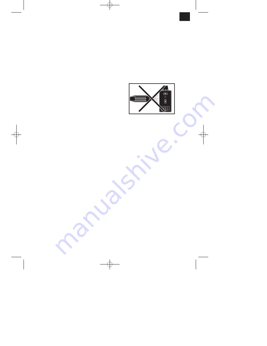
Dismantle the laser before you clean the machine
with water.
10. Maintenance
앬
Clean off all dust and soiling from the machine at
regular intervals, preferably with a cloth or a
brush.
앬
Lubricate all moving parts at regular intervals.
앬
Do not use any aggressive cleaning agents to
clean plastic parts.
앬
Clean off any soiling on the trough (3) and
cooling agent pump (13) at regular intervals,
otherwise the diamond cutting wheel (2) may not
be cooled as required. To empty the trough,
remove the rubber stopper (36) and drain the
water into a suitable vessel (Fig. 15).
11. Ordering replacement parts
Please quote the following data when ordering
replacement parts:
앬
Type of machine
앬
Article number of the machine
앬
Identification number of the machine
앬
Replacement part number of the part required
For our latest prices and information please go to
www.isc-gmbh.info
Anleitung_RT_SC_570_L_SPK7:_ 04.06.2008 13:55 Uhr Seite 11


