background image


Page 2 of 16 

Drawing   : - TPC181 
Issue 

: - 11 

Date 

: - 24/11/16 


UNPACKING 


Carefully remove the CD100 dehumidifier unit from its transit box and visually 
check  for  signs  of  transit  damage.  If  there  is  evidence  of  damage  DO  NOT 
attempt  to  operate  the  unit,  call  your  supplier  for  advice.  Do  not  discard  the 
packing; it will be useful when transporting the dehumidifier unit in the future. 


INTRODUCTION 


Dehumidifiers remove moisture from the air that is circulating through the unit. 
The  resulting  reduction  of  relative  humidity  helps  prevent  rust,  rot,  mould, 
mildew  and  condensation  within  the  room,  shelter  or  other  enclosed  spaces 
where the dehumidifier is used. 
A  dehumidifier  consists  of  a  motor-compressor  unit,  a  refrigerant condenser, 
an  air  circulating  fan,  a  refrigerated  evaporator,  a  means  for  collecting  and 
disposing  of  the  condensed  moisture  and  a  cabinet  to  house  these 
components. 
The fan draws the moist room air through the cold evaporator coil which cools 
the air below its dew point. Moisture forms on the evaporator and is collected 
in  the  condensate  tray  then  lead  away  to  a  permanent  drain. The cooled  air 
then  passes  through  the  hot  condenser,  where  it  is  re-heated  with  the  same 
energy removed during the cooling phase and the addition heat derived from 
the  compressor.  The  air  is  therefore  discharged  into  the  room  at  a  slightly 
higher  temperature  but  at  a  lower  relative  humidity  than  that  at  which  it 
entered  the  unit.  Continuous  circulation  of  room  air  through  the  dehumidifier 
gradually reduces the relative humidity of the room. 
The CD100 dehumidifier is a rugged reliable drying unit designed to operate 
effectively  over  a  broad  range  of  temperature  and  humidity  conditions.  A 
powerful  and  reliable  active  hot  gas  defrost  system,  controlled  by  an 
electronic  timer,  guarantees  positive  de-icing,  thereby  optimizing  at  low 
temperatures. 
The  unit  incorporates  a  welded  steel  chassis  and  is  finished  in  vinyl  coated 
steel covers for resilience to damage caused by rough handling. 


Summary of Contents for CD100E

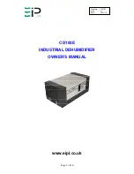
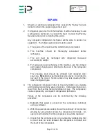
Page 1: ...Page 1 of 16 Drawing TPC181 Issue 11 Date 24 11 16 CD100E INDUSTRIAL DEHUMIDIFIER OWNER S MANUAL www eipl co uk...

Page 2: ...e moist room air through the cold evaporator coil which cools the air below its dew point Moisture forms on the evaporator and is collected in the condensate tray then lead away to a permanent drain T...

Page 3: ...sed in products manufactured by Ebac Industrial Products Ltd is as follows R134a 1300 R407c 1610 For type and weight of refrigerant contained in this unit please refer to the product data label MODEL...

Page 4: ...gle phase fused power supply As follows Brown Live Blue Neutral Green Yellow Earth ground ALARM WIRING Plug L Normally Open Contacts Plug N Close on Humidity Rise Plug E Earth DRAINAGE Connect a 15mm...

Page 5: ...motor is able to take stalled current without burning out the motor windings TEST FOR CORRECT OPERATION 1 Set the adjustment humidistat to maximum 2 Switch the machine to the on position this will re...

Page 6: ...e the build up of ice No attempt should be made to cut open any part of the refrigeration circuit due to high pressures and gas involved If the unit is switched off at the mains power supply for any r...

Page 7: ...he conditions within the area to be dried The following table can be used as a guide APPLICATION HUMIDISTAT SETTING FACTORIES 60 WAREHOUSES 50 BASEMENTS 50 DEFLOODING 40 INDICATOR PANEL The CD100 is f...

Page 8: ...umidistat This humidistat incorporates a knob pointer and a graduated scale which gives the customer the facility to select the desired humidity level within the room being dried The humidistat is pos...

Page 9: ...ve 25 C the coil may be covered with droplets of water rather than frost Partial frosting accompanied by frosting of the thin capillary tubes indicates loss of refrigerant gas or low charge 4 Check al...

Page 10: ...the refrigerant compressor The charging stub should be crimped and rebrazed after servicing NEVER allow permanent service valves to be fitted to any part of the circuit Service valves may leak causing...

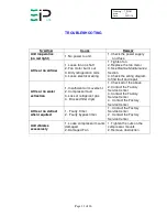
Page 11: ...diagram to find fault and repair Little or no water extraction 1 Insufficient air movement 2 Compressor fault 3 Loss of refrigerant gas 4 Blocked filter dryer 1 Check all of the above 2 Contact the F...

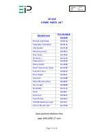
Page 12: ...20810 Filter Dryer 3020904 Fan Motor 3030129 Solenoid Coil 3030402 Rotary Switch 3030555 Drain Tube Heater Tape 3031629 Indicator Lamp 3032203 Float Switch 3033021 Contactor 3034389 Panel Mounting Plu...

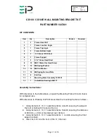
Page 13: ...12 6 End Cap 13 1 Mounting Fame Assembly 1027301 14 1 Installation Drawing 5060117 Assembly Instructions With reference to the table above unpack the Mounting Frame Kit and check for completeness With...

Page 14: ...e bracket onto the wall 6 Secure the bracket to the wall 7 With reference to Drawing 5060117 Position the CD100 CD100E onto the Wall Mounted Bracket 8 Using Item 6 assemble items 1 and 2 ensuring the...

Page 15: ...d This product contains fluorinated greenhouse gases covered by the Kyoto Protocol The refrigeration system is hermetically sealed The Global Warming Potential GWP of refrigerants used in products man...

Page 16: ...ww eipl co uk sales eipl co uk American Sales Office Ebac Industrial Products Inc 700 Thimble Shoals Blvd Suite 109 Newport News Virginia 23606 2575 USA Tel 01 757 873 6800 Fax 01 757 873 3632 www eba...

Reviews: