EK-Quantum Velocity 2 D-RGB AM4, User Manual
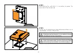
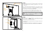
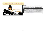
The EK-Quantum Velocity 2 D-RGB AM4 user manual is available for free download on our website. This comprehensive manual provides step-by-step instructions to ensure a hassle-free installation and optimal performance of your product. Find the download link to the manual on our website 88.208.23.73:8080.
Share
Download


Reviews:
No comments
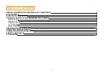
Related manuals for Velocity 2 D-RGB AM4

D20MX
Brand: GE Pages: 146

PUZZLE-IN003B
Brand: IEI Technology Pages: 86

Lite N42B1P Series
Brand: Dahua Technology Pages: 14

B9.1ut
Brand: Zoom Pages: 88

RCO-3000 Series
Brand: C&T Solution Pages: 96

HHM Series HHM2245SA1
Brand: TDK Pages: 2

509-8629-00
Brand: SurfControl Pages: 2

NC-AP111
Brand: NC-link Pages: 20

NVRPRO
Brand: Dahua Pages: 113

CNPS 4X
Brand: ZALMAN Pages: 16

I-87K Series
Brand: ICP DAS USA Pages: 31

CORE 2 DUO E4000 - 3-2008
Brand: Intel Pages: 122

X-NUCLEO-EEPRMA1
Brand: ST Pages: 22

JV80
Brand: Roland Pages: 224

Nova M3 MFN300
Brand: NovaStar Pages: 16

EdgeSafe M40G1AC
Brand: Garland Pages: 159

QSW-3216R-8S8T
Brand: QNAP Pages: 11

QPE6105A
Brand: Qorvo Pages: 15


