background image

TECNOEKA Srl ______________________________________________________________ use and instruction manual  

page 8 __________________________________________________________________________________________ 

Connecting  th

Connecting  th

Connecting  th

Connecting  the  power  cable

e  power  cable

e  power  cable

e  power  cable  (for  mod.  EKF  664  UD/003)-  To  reach  the  power  terminal  board 

remove  the  left  side  of  the  appliance.  Loosen  the  cable-clamp  on  the  back  (at  the  bottom)  of 
the  appliance  and  pass  the  cable  through  up  to  near  to  the  terminal  board.  Locate  the  leads 
against the terminal board so that the earth  lead is the last  to detach from its  terminal in the 
event of reverse pulling. Connect the phase 

phase 

phase 

phase lead to the terminal marked “

“L”

L”

L”

L”, the neutral 

neutral 

neutral 

neutral lead to 

the  terminal  marked  “N”

“N”

“N”

“N”  and  the  earth 

earth 

earth 

earth  lead  to  the  terminal  marked 

.  Tighten  the  cable 

gripper and re-fit the left side-panel of the appliance. 
The  appliance  must  be  connected  to  an  equipotential  system

equipotential  system

equipotential  system

equipotential  system  whose  efficiency  must  first  be 

checked according to current legal regulations. 
This connection must be made between different appliances by using the appropriate terminal 
marked with the symbol  . The equipotential conductor must have a minimum diameter of 2,5 
mm

2

 The equipotential terminal is at the rear of the appliance. 

    
Safety ther

Safety ther

Safety ther

Safety thermal breaker

mal breaker

mal breaker

mal breaker - The appliance has a manually reset safety thermal breaker. It protects 

against excessive dangerous over-temperatures which could be accidentally generated inside the 
appliance.  If  the  device  is  tripped,  it  interrupts  electrical  power  to  the  appliance  and  thus 
prevents it from operating. To access this device, remove the left side-panel of the appliance.    


5. 

5. 

5. 

5. Use instructions (for the user)

Use instructions (for the user)

Use instructions (for the user)

Use instructions (for the user)    


This  appliance  is  not  intended  for  use  by  persons  (including  children)  with  reduced  phycal, 
sensory  or  mental  capabilities,  or  lack  of  experience  and  knowledge.  Unless  they  have 
beengiven  supervision  or  instruction  concerning  use  of  appliance  by  a  person  responsible  for 
their safety. Children should be supervised to ensure that they do not play with the appliance. 
For first use, we advise you to let the appliance to run load-free at maximum temperature for 
about one hour. In this way, any unpleasant smells due to thermal insulation and residual work 
grease  are  eliminated.  This  appliance  must  be  used  solely  for  the  purpose  for  which  it  was 
expressly designed, i.e. cooking  foods in the oven. Any other use is considered unsuitable. 
The  appliance  can  be  used:  for  all  oven  cooking  of  deserts,  pizzas,  meat,  fish,  vegetables,  as 
well as for gratinating, and for re-conditioning cooled and frozen foods. When placing food in 
the cooking compartment, leave a space of at least 40 mm between pans in order not to over-
obstruct  air  circulation.  Do  not  use  pans  with  higher  than  necessary  edges:  edges  are  barriers 
which prevent the circulation of hot air. Warm up the oven before every cooking operation to 
obtain maximum uniformity. Do not salt foods in the cooking compartment. 


6. 

6. 

6. 

6. Residual risks (for the user)

Residual risks (for the user)

Residual risks (for the user)

Residual risks (for the user)    


After a cooking operation, open the door cautiously, to avoid a violent outflow of heat which 
could cause burns. While the oven is in operation, pay attention to the hot zones (marked on 
the  appliance)  of  its  external  surfaces.  Place  the  machine  on  a  bench  or  similar  support,  at  a 
height  of  at  least  85  cm  from  the  floor.  The  bench  or  support  must  be  able  to  support  the 
weight of the machine  and house it correctly. The appliance contains electrical parts and must 
never  be  washed  with  a  jet  of  water  or  steam.  The  appliance  is  electrically  connected:  before 
attempting any cleaning operation, cut power to the appliance. To prevent incorrect connection 
of  the  appliance,  the  relevant  electrical  and  water  connections  are  marked  by  identification 
plates. If the internal glass panel of the door has to be cleaned, it must be dismantled with the 
help of a second operator: one operator supports the glass panel, while the other unscrews its 
securing screws. 

Summary of Contents for EKF 616 U

Page 1: ...64 UD UD UD UD EKF EKF EKF EKF 664 UD 664 UD 664 UD 664 UD HT HT HT HT EKF 664 UD 003 EKF 664 UD 003 EKF 664 UD 003 EKF 664 UD 003 EKF EKF EKF EKF 616 UD 616 UD 616 UD 616 UD EKF EKF EKF EKF 616 UD 616 UD 616 UD 616 UD HT HT HT HT rev rev rev rev 2 2 2 2 TECNOEKA S r l Via Marco Polo n 11 35010 Borgoricco Padova Italy Tel 39 049 9300344 39 049 5791479 Fax 049 5794387 www tecnoeka com E mail info t...

Page 2: ...l page 2 __________________________________________________________________________________________ X Sgq PRODOTTI 1 FORNI FORNO ELETTRICO LEka MANUALI D USO Forno Elettrico 40 60 90 LEka Lingua Inglese NUOVA GAMMA EF Instruction manual EKF 711 UD EKF 664 UD HT EKF 664 UD_003 EKF 616 UD HT GB rev 2 doc ...

Page 3: ...1 UD 711 UD 711 UD 711 UD EKF 664 UD EKF 664 UD EKF 664 UD EKF 664 UD EKF 664 UD EKF 664 UD EKF 664 UD EKF 664 UD HT HT HT HT EKF 664 UD 003 EKF 664 UD 003 EKF 664 UD 003 EKF 664 UD 003 EKF 616 UD EKF 616 UD EKF 616 UD EKF 616 UD EKF EKF EKF EKF 616 UD 616 UD 616 UD 616 UD HT HT HT HT TECNOEKA Srl declares that the mentioned above products meet the following safety regulations Low voltage directiv...

Page 4: ..._____________________________ Index Index Index Index 1 Technical service 2 General warnings 3 Technical specifications 4 Instructions for the installer 5 Use instructions for the user 6 Residual risks for the user 7 How to use the control panel 8 Oven cooking 9 Cleaning 10 Maintenance 11 Technical service 12 Information to the consumers 13 Wiring layout 14 The Warranty ...

Page 5: ... instructions shall release Improper or incorrect use and failure to observe the installation instructions shall release Improper or incorrect use and failure to observe the installation instructions shall release the manufacture from all responsibility the manufacture from all responsibility the manufacture from all responsibility the manufacture from all responsibility In this connection the dir...

Page 6: ...tion make sure of the following the voltage and frequency values of the power supply system match the values on the technical data plate affixed on the appliance the limiting valve and the system are able to support the appliance s load see the technical data plate the power sup the power sup the power sup the power supply system has an adequate earth connection according to current legal ply syst...

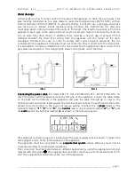
Page 7: ...te system thus stopping the steam coming back out of the drain FIG FIG FIG FIG 1 1 1 1 FIG FIG FIG FIG 2 2 2 2 Connecting the power cable Connecting the power cable Connecting the power cable Connecting the power cable for modd EKF 711 UD EKF 664 UD HT EKF 616 UD HT To reach the power terminal board remove the left side of the appliance Loosen the cable clamp on the back at the bottom of the appli...

Page 8: ...h reduced phycal sensory or mental capabilities or lack of experience and knowledge Unless they have beengiven supervision or instruction concerning use of appliance by a person responsible for their safety Children should be supervised to ensure that they do not play with the appliance For first use we advise you to let the appliance to run load free at maximum temperature for about one hour In t...

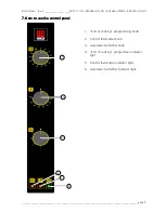
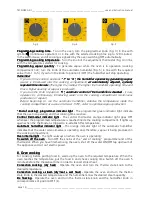
Page 9: ...__________________ page 9 7 7 7 7 How to use the control panel How to use the control panel How to use the control panel How to use the control panel 1 End of cooking programming knob 2 Control thermostat knob 3 Automatic humidifier knob 4 End of cooking programmer indicator light 5 Control thermostat indicator light 6 Automatic humidifier indicator light 1 2 3 4 5 6 ...

Page 10: ...he temperature inside the cooking compartment at a value of at least 110 C order to optimise vapour production End of cooking programmer indicator light End of cooking programmer indicator light End of cooking programmer indicator light End of cooking programmer indicator light The programmer green indicator light indicate that the oven is operating and that cooking time is active Control thermost...

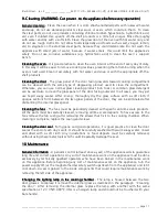
Page 11: ...ng outward In all cases you may just use tepid soapy water After rinsing thoroughly dry the glass surface with a soft cloth If opaque sections form between the two glass panels of the door they can be eliminated after dismantling the internal glass panel Cleaning the fans Cleaning the fans Cleaning the fans Cleaning the fans The fans must be periodically cleaned with specific anti lime scale produ...

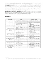
Page 12: ...rrective action Control panel completely off the oven does not work Incorrect electric connections to the mains Check the mains connection No mains voltage Restore mains voltage Thermal break safety device tripped Reset the thermal break safety device Cooking cycle set the oven does not work Door open or ajar Close the door Damaged magnetic sensor Contact a qualified technician to repair the senso...

Page 13: ...ser can contact Tecnoeka by calling the telephone numbers on the cover or going to www tecnoeka com www tecnoeka com www tecnoeka com www tecnoeka com 12 12 12 12 Informations to the consumers Informations to the consumers Informations to the consumers Informations to the consumers Further to Directive 2002 96 EC the symbol of the crossed rubbish skip on the appliance means that at the end of its ...

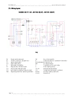
Page 14: ...EKF 616 UD EKF 616 UD EKF 616 UD EKF 616 UD HT HT HT HT Key Key Key Key M Power terminal board Pr End of cooking programmer T1 Safety thermostat T2 Oven thermostat U Automatic humidifier S1 Programmer indicator light S2 Thermostat indicator light S3 Automatic humidifier indicator light IM Operating direction reversing element MI Door microswitch E Solenoid valve for automatic humidifier B1 B2 B3 B...

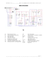
Page 15: ...nal board Pr End of cooking programmer T1 Safety thermostat T2 Oven thermostat U Automatic humidifier S1 Programmer indicator light S2 Thermostat indicator light S3 Automatic humidifier indicator light IM Operating direction reversing element MI Door microswitch E Solenoid valve for automatic humidifier B1 B2 Contactor coil B R Contactor Relais T Transformer for oven lamp L Oven lighting lamp V1 V...

Page 16: ...justments and or maintenance and or repairs carried out by unauthorised personnel and or with non original spare parts 8 inadequate or careless maintenance of the product in contrast with the user s handbook supplied with the product 9 damages caused by fire natural disasters and accident as well as by any cause not attributable to TECNOEKA SRL The warranty explicitly excludes The warranty explici...

Reviews: