_ Hob _ rev. 0 _____________________________________________________________________ KP 96 – KTP 96 _
_ CATEGORY II2H3+ _ GB __
0705
______________________________________________________ page 11 _
an H distance from the base, respecting
the value indicated in table 1. Tighten
screw “V” again.
-
Having replaced the main nozzles of the
burners and having adjusted the primary
air, seal the adjusted tools with varnish.
Reassemble all the components removed in
reverse order and stick the new data on the
technical data plate.
N.B. Removing the rear panel of the appliance, all the re-assembly operations of the burners
can be simplified.
Minimum level adjustment
- Burner minimum levels are preset for methane gas (G20) operation. If
operating on liquid gas (G30/G31) proceed as follows: ignite the burner at minimum position, and, using
a screwdriver, fully tighten the by-pass adjustment screw at the side of the shank of the relevant tap.
Check if the flame remains stable and uniform – to help you check, rapidly turn the tap knob from
maximum to minimum position. When you have finished adjusting the by-pass valve, seal it with red
paint. Make sure you fit a plate with the new installation data. After having set the by-pass screw, seal it
with red varnish.
Gas pressure (mbar)
Type of gas
Normal
Max.
Min.
Table 1
G30 30
35
20
G31 37
45
25
G20 20
25
17
Main nozzles
diameter
(1/100 mm)
By-pass screw
nozzles diameter
(1/100 mm
)
H distance for air
adjustment
(mm)
Consumption calculated with
gross heat values
Nominal
thermal
capacity
(kW)
Reduce
d
thermal
capacit
y (kW)
G30/G31
30/37mba
r
G20
20mbar
G30/G31
30/37mba
r
G20
20mbar
G30/G31
30/37mba
r
G20
20mbar
G30
30mbar
(g/h)
G31
37mbar
(g/h)
G20
20mbar
(l/h)
Triple
crown
burner Nr.
1
3.6 1.8 90 140 74
Regul. 6 6 262
257
343
Fast burner
Nr. 3
3.1
0.95 83 130 50
Regul. 6 4 226
222
296
Semi-fast
burner Nr.
1
2.7 0.6 77 119 40
Regul. 6 4 197
193
257
7. Instructions for use
-
Cook-top control panel and use
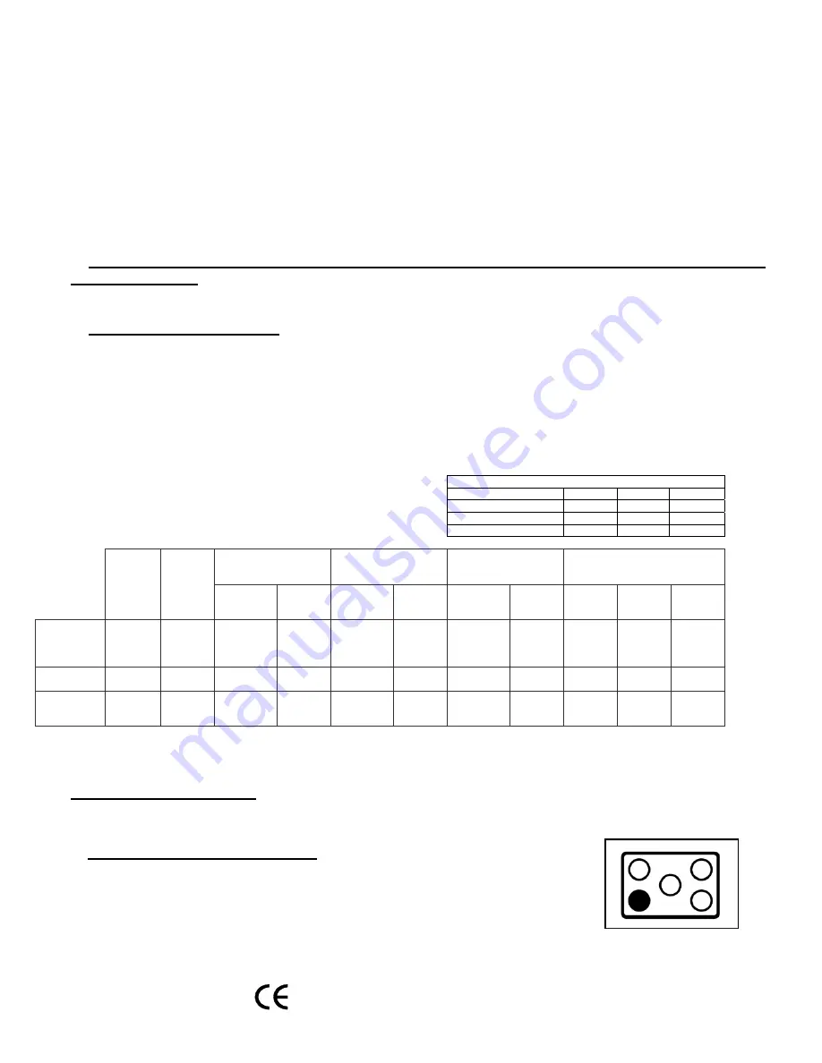
- On the control panel, 4 empty and
one fully coloured circles are placed next to each gas cock knob of the
cook-top (Fig. 6). The fully coloured one indicates the position of the
gas burner that is commanded by the knob in question.
Fig. 6


