background image


3.3 Unpacking the appliance 

Remove  the  packaging  before  installation.  It consists of a wooden  pallet  supporting the  appliance and  a 
cardboard  casing  protecting  it.  Ensure  the  appliance  has  not  undergone  any  damage  during  transport; 
otherwise immediately alert your dealer and/or carrier. 

3.4 Removal of the protective film 

Before  using  the  appliance  accurately  remove  the  special  film  protecting  the  stainless  steel  components, 
avoiding  glue  residues  on  the  surfaces;  if  required,  immediately  remove  them  using  an  appropriate  non 
flammable  solvent.  Do  not  use  any  tools  that  might  scratch  the  surfaces  or  any  acid-based  or  abrasive 
detergents.  

3.5 Protective film/package disposal 

TECNOEKA has been committed for years to increasing the environmental compatibility of its equipment, 
with  continuous  efforts  to  reduce  energy  consumption  and  waste.  TECNOEKA  intends  to  protect  the 
environment  and  recommends  to  dispose  of  all  different  types  of  material,  in  the  appropriate  separate 
collection containers. 
The protective film and packaging must be disposed of in strict compliance with the regulations in force in 
the  country  of  installation  of  the  appliance.  The  various  materials  (wood-paper-carton-nylon-metal  tacks) 
that may comprise the packaging are potentially dangerous and must be kept out of reach of children and 
animals; they must be duly separated and delivered to the respective collection centres (recycling centres). 
In any case please adhere to the local environmental protection regulations. 
 
3.6 Placement 
 
Check the place of installation making sure that the transit areas (any doors and corridors) are sufficiently 
wide and the floor supports the appliance’s weight (the appliance’s weight and dimensions with/without 
pallets  are  provided  in  the  attached  “Technical  Data  Sheet”).  The  appliance  must  be  transported  with 
mechanical means (e.g. pallet jack). The installation rooms must be well-ventilated with permanent aeration 
vents;  must  be  equipped  with  the  proper  electrical  and  hydro  systems,  built  in  accordance  with  the 
standards related to facilities and workplace safety in the country of installation. 
The maximum working height, referring to the highest surface level, must be 1.6 metres from the floor. 

After installing the appliance, if required, apply the suitable adhesive symbol 

(supplied) at a height of 

1.6  metres.  To  favour  air  circulation  around  the  appliance,  leave  a  space  of  about  10  cm  between  the 
appliance sides and the surrounding walls (or other appliance), and between the back and the back wall 
(see the attached “Technical Data Sheet”). The appliance must be positioned so that the rear wall is easily 
accessible to set up various electrical connections and to carry out any possible maintenance. Do not install 
the appliance near any equipment that may reach high temperature values (e.g. deep fryers).  
Should the appliance be installed near walls, shelves, counters and the like, these must be non-flammable 
or heat-resistant; otherwise, they must be protected by adequate fire retardant coating. Accordingly, it is 
indispensable to act in compliance with the fire prevention regulations in force.  
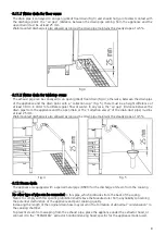
Cooking  produces  hot  smoke/vapour  and  odours  which  are  extracted  through  the  suitable  vent  device 

located  at  the  top  of  the  appliance  and  marked  with  the  symbol 

.It  is  recommended  to  place  the 

appliance  under  an  extraction  hood  or  to  use  the  suitable 

TECNOEKA.

  condensation  hoods  in  order  to 

convey the smoke/vapour to the outside.


Warnings 


Make sure there are no objects and/or materials obstructing the oven’s exhaust device. 
 
The hot smoke/vapour produced during cooking must run freely out of the exhaust device in order not to 
compromise the regular operation of the oven. 
 
Inflammable materials must not be left near the oven’s exhaust device. 

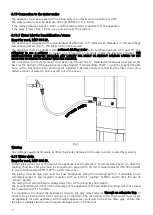
3.6.1 Table top oven placement  

The appliance must be placed in a perfectly horizontal position on a table or similar support; never on the 
floor. To facilitate oven levelling, the feet are adjustable in height. 
For  safety  reasons  it  is  recommended  to  use  the  specific  table  produced  by 

TECNOEKA

;  otherwise  the 

dimensions and weight of the appliance must be taken into account.  
The appliance is unsuitable for recessed installation and cannot work without the 4 supporting feet. 

Summary of Contents for MKF 1016 S

Page 1: ...ION OF ORIGINAL INSTALLATION AND MAINTENANCE MANUAL SMART OVENS MKF 464 S MKF 416 S MKF 511 S MKF 664 S MKF 664 SP MKF 621 S MKF 616 S MKF 711 S MKF 1064 S MKF 1021 S MKF 1016 S MKF 1111 S MKF 1664 S MKF 2011 S ...

Page 2: ...________________________ 7 3 11 Water drain______________________________________________________________________ 7 3 11 1 Water drain for floor ovens _______________________________________________________ 8 3 11 2 Water drain for tabletop ovens ____________________________________________________ 8 3 12 Steam drain______________________________________________________________________ 8 4 MAINTEN...

Page 3: ...ny ingress of water might affect its safety Before maintenance or cleaning disconnect the appliance from the power supply mains and let it cool In the event of failure or poor operation switch off the appliance close the water supply cock disconnect the power supply and contact an authorised Support Centre Any modification to the electrical system that might be required to install the appliance mu...

Page 4: ...ance with the standards related to facilities and workplace safety in the country of installation The maximum working height referring to the highest surface level must be 1 6 metres from the floor After installing the appliance if required apply the suitable adhesive symbol supplied at a height of 1 6 metres To favour air circulation around the appliance leave a space of about 10 cm between the a...

Page 5: ...ure that the wheels of the tray trolley inserted in the cooking chamber are raised off the floor by not more than 5 mm and that the trolley is supported by the guides at the bottom of the appliance The tray trolley must be moved using the supplied grip The grip must be inserted into place at the front of the trolley up to the stopping point The tray trolley must be inserted inside the cooking cham...

Page 6: ...e gland up to the terminal board Prepare the conductors for the connection with the terminal board so that the earth conductor is the last to be extracted from its terminal should the cable be accidentally pulled The cable connection must be type Y and the insulation of the cable sheath must match type H07RN F The correct section of the cable is shown on the diagram of the power supply terminal bo...

Page 7: ...6 Mod MKF 416 S MKF 464 S MKF 511 S Mod MKF 616 S MKF 664 S MKF 664 SP MKF 711 S Mod MKF 621 S Mod MKF1016 S MKF 1064 S MKF 1111 S Mod MKF 1021 S Mod MKF 1664 S MKF 2011 S ...

Page 8: ...topcock installed in between before connecting the filter drain off a certain amount of water to flush any dirt out of the hose Fig 1 Warning Any damage caused by limescale or other chemicals contained in the water are not covered by warranty 3 11 Water drain Exept for mod MKF 664 SP A drain pipe comes out of the rear of the appliance see the attached Technical Data Sheet to drain the cooking cham...

Page 9: ...from the appliance and the open drain or the collection vessel of the drain duct pipe must be at least 25 mm Wall mounted discharge is also allowed as long as the drain pipe maintains the steady slope of 4 5 Fig 4 Fig 5 3 12 Steam drain The appliance is equipped with a special metal pipe DN30 for the discharge of steam from the cooking chamber No other type of pipe can be connected to this pipe wh...

Page 10: ...board Safety thermostat Capacitors Humidification solenoid valve Magnetic door sensor control transmission relay Cam programmer Motor reversing gear Humidification piping fittings unit Removing the right side Magnetic door sensor door opening to the left Control thermostat bulb door opening to the right 12 way electrical wiring connector for controls on door Removing the control protection box on ...

Page 11: ...sition of the 2 hinges upper and lower of the door and or the cross shaped handle nose projection by doing the following Loss of tightness on the hinges side With the door closed loosen the 6 screws securing the lower hinge 3 screws and upper hinge 3 screws of the door push the door slightly to the side of the hinges so that the inner glass leans on the front gasket hold the door slightly pressed ...

Page 12: ...y contact Tecnoeka on the numbers shown on the cover or refer to the website www tecnoeka com Type of fault Cause of the fault Corrective action Control panel warning lights totally off The oven does not work Non compliant connection to the power mains Check the connection to the mains No mains voltage Restore the power supply voltage Safety thermal device triggered Restore the safety thermal devi...

Page 13: ...hase Including the event in which the customer is unable to produce the invoice receipt or tax receipt as proof of purchase meaning that the terms outlined above are not complied with the warranty is expressly forfeited in the following cases 1 Faults or breakdowns of components caused by transport 2 Damage deriving from inadequate electrical hydraulic and gas supply systems compared to that provi...

Page 14: ...AW AND COMPETENT COURT Supply relationships will be governed by Italian law with the express exclusion of the private international law standards and the Vienna Convention on Contracts for the International Sale of Goods of 11 4 1980 Any dispute will be settled exclusively by the Court of Padua Without prior notice and liability for Tecnoeka Srl the products presented in the manual may be subject ...

Page 15: ...14 ...

Page 16: ...15 REV 0 ...

Reviews: