User Guide CC9-SAMBA •
CompactPCI®
Pentium M CPU Board
© EKF -29- ekf.com
Universal Serial Bus (USB)
The CC9-SAMBA is provided with six USB ports, all of them are USB 2.0 capable. Two USB interfaces
are routed to front panel connectors, two ports are feed to the expansion board interface connectors
PEXP, and two further ports are optionally available for rear I/O across the J2/P2
CompactPCI
connector.
The front panel USB connectors can source up to 0.5A/5V each, over-current protected by two
electronic switches. Protection for the USB ports on the expansion interface and on the rear I/O
connector is located on the CCA-LAMBADA and the CCR-RIO respective. The USB controllers are
integrated into the ICH4.
LPC Super-I/O Interface
In a modern system, legacy ports as PS/2 keyboard/mouse, COM1/2 and LPT have been replaced by
USB and Ethernet connectivity. The 1.4MB floppy disk drive has been swapped against LS-120 or CD-
RW drives, attached to the IDE connector, or USB memory sticks. Hence, the CC9-SAMBA is virtually
provided with all necessary I/O ports. However, for compatibility purposes the CC9 is additionally
equipped with a simple Super-I/O chip, for optional rear I/O of PS/2 keyboard/mouse and COM1 (TTL
level only) across the J2/P2 CPCI connector. The Super-I/O controller resides on the local LPC bus (LPC
= Low Pin Count interface standard), which is a serialized ISA bus replacement.
As an alternative, EKF offers the CCA-LAMBADA, an expansion module to the CC9-SAMBA, featuring
all classic Super-I/O functionality. The CCA-LAMBADA is a 3U Eurocard with a 4HP (single) width front
panel. Access to the connectors PS/2 (mouse, keyboard), COM, USB and audio in/out is given directly
from the front panel. The CCA-LAMBADA connects to the CC9-SAMBA across the connector PEXPT or
PEXPB. The CCA-LAMBADA can be attached either to the top or to the bottom of the CC9-SAMBA.
Watchdog/Reset
The CC9-SAMBA is provided with two MAX6705 supervisor circuits, which monitor the supply
voltages 2.5V, 3.3V and 5V, and generate a power-on reset signal. The manual push-button reset is
also passed through the MAX6705s for appropriate pulse conditioning.
The reset manual push-button is situated at the front panel. The button is indent mounted behind the
front and requires a tool, e.g. pen to be pressed, preventing from being inadvertently activated. The
push button reset signal is routed across a PLD (programmable logic device) and could be passivated
on customers request.
The healthy state of the CC9-SAMBA is signalled by the LED PWR integrated into the reset push-
button. As soon as this LED begins to shine all power voltages are well and the reset signal has been
deasserted.
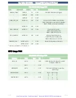
Another feature is the watchdog function, which can be programmed by software. The behaviour of
the MAX6705 watchdog is partially defined by the PLD, which controls whether the watchdog is
activated. The related software (e.g. BIOS, application program) must trigger the watchdog by
toggling the GPO21 signal of the ICH4.
Artisan Technology Group - Quality Instrumentation ... Guaranteed | (888) 88-SOURCE | www.artisantg.com


