Section 3 -
Page 1 of 6
3121-9001-0167_EN.03.00_QT_Manual
04/2016
Section 3
Setting up the System
Quo-Test
11:32 21/06/13
Setup
File
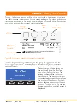
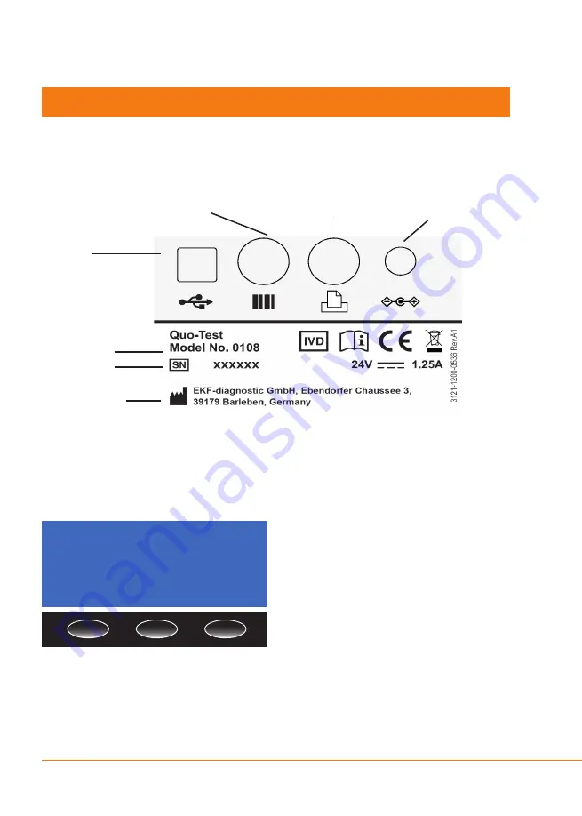
Connect the barcode scanner and the printer (optional) to the analyzer by pushing
the cables into the connectors on the rear panel. Make sure the printer and barcode
scanner are connected to the correct ports as shown in Figure 2 below. If the printer
is no longer required, disconnect it from the analyzer.
Figure 2: Connection panel on the rear of the analyzer.
Connect the power supply to the analyzer and plug the supply cord into the
mains supply (100-240v AC 50-60Hz). Ensure that the supply has a protective
earth connection.
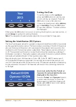
Once the analyzer has warmed up
the screen will show the Quo-Test
logo, this is the home screen. The
keypad under the blue screen has
three buttons. The text on the screen
immediately above each button shows
the function of that button. If there is
no text above a button, then it has no
function. The functions of the buttons
change, depending on which screen is
displayed.
USB Port
Model No.
Manufacturer
Serial No.
Barcode
Scanner Port
Printer
Port
DC
Power Supply
Summary of Contents for Quo-Test
Page 1: ...User Manual Quo Test Diagnostics for life ...
Page 32: ...3121 9001 0167 ...


