background image

Application manual 

                               Interface for Load monitoring and control EK- CF2-TP 


Revision 1.0.0 - Update: 04/07/2017 

© EKINEX S.p.A. 

– All rights reserved 

MAEKCF2TP_IT 

Pag. 27 


9. 

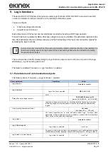
Logic functions 

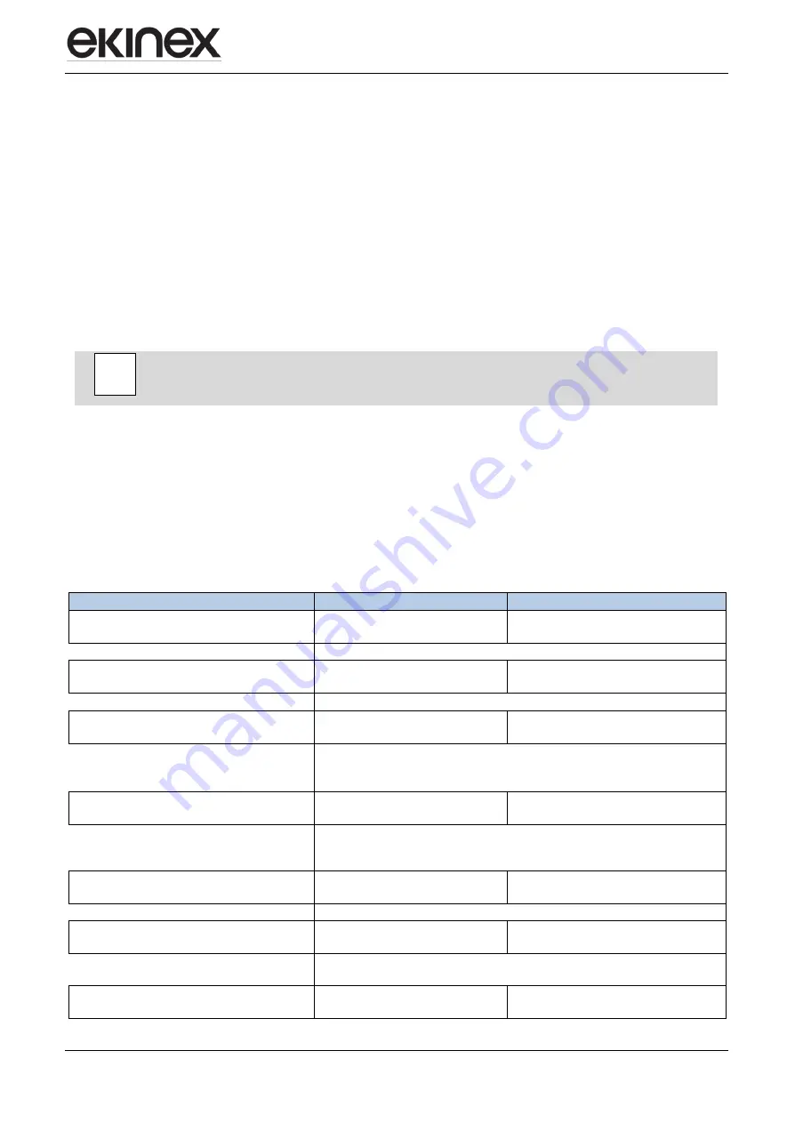
The device EK-CF2-TP allows uYesng some useful logic functions (AND, OR, NOT and excluYesve OR) 
in order to implement complex functions in the building automation system.  

You can configure: 


4 channels of logical functions 


4 inputs for each channel 

Each object value, if deYesred, can be individually inverted by inserting a NOT logic operator. 

For each channel, a parameter 

Delay after bus voltage recovery 

is available: this parameter represents the 

time interval between the bus voltage recovery and the first reading of the input communication objects for 
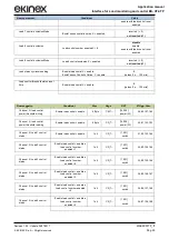
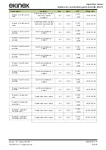
evaluating the logic functions.  


In case of incorrect connection of the input communication object or electrical trouble on bus resulting in a 
failed input reading request, the logic output of the corresponding channel can be calculated by setting 
the input values to default.


The communication function representing the logic function output is sent on the bus on event of change; 
alternatively, a cyclic sending can be set.


The folder is enabled if: 

General


Logic functions

 = enabled. 

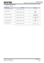
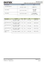
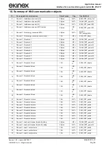
9.1. Parameters and communication objects 

The folder is active if: General 

 Logic functions = enabled. 

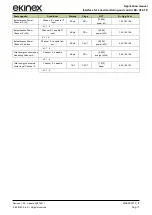
Nome parametro 

Condizioni 

Valori 

Logic function 


disabled

 / enabled 


Logic operation 


Logic  Function = enabled 

OR

 / AND / XOR 


XOR  

Delay after bus voltage  recovery 


00:00:04.000 hh:mm:ss.fff 

[campo 00:00:00.000 … 00:10:55.350] 


Intervallo di tempo che intercorre tra il ripristino della tenYesone bus e la prima 
lettura degli oggetti di comunicazione di input per la valutazione delle funzioni 
logiche. 

Output cycling trasmission interval 


not send 

[altri values 

30 s … 120 min] 


Not  send  Yes

gnifica  che  lo  stato  dell’output  della  Logic    Function  viene 

aggiornato  sul  bus  solamente  ad  una  variazione.  Intervalli  diverYes  implicano 
l’invio ciclico sul bus dello stato dell’output. 

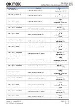
Logic objet x 


disabled

 / enabled 


Logic Object negated  


Logic objet x = enabled 

no

 / Yes 


Negando lo stato logico dell’input corrispondente, è posYesbile realizzare logiche 
combinatorie articolate. Esempio: Output=(NOT(Logic objet 1) OR Logic objet 2). 

Logic object  x read at startup 


Logic objet x = enabled 

no

 / Yes 


Summary of Contents for EK-CF2-TP

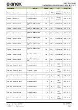
Page 1: ...manual Interface for Load monitoring and control EK CF2 TP Revision 1 0 0 Update 04 07 2017 EKINEX S p A All rights reserved MAEKCF2TP_IT Pag 1 APPLICATION MANUAL EK CF2 TP INTERFACE FOR LOAD MONITORING AND CONTROL ...

Page 2: ...ation objects 8 6 3 2 Cyclic sending 8 7 Operating parameters 9 7 1 General parameters 9 6 3 3 TA configuration 10 7 2 Channel configuration 11 7 3 Configuration of a power threshold function 12 7 4 Configuration of a load control function 13 8 Application program for ETS 15 8 1 About EK CF2 TP 15 8 2 General settings 16 8 3 Channel information 18 8 4 Measurement channel X 19 8 5 Thresholds Y Chan...

Page 3: ...tures and ETS application programming For installation mechanical and electrical details of the device please refer to the technical description datasheet Application manual and ETS application programs are available for download at www ekinex com Document Filename verYeson VerYeson Device reviYeson Latest update Technical datasheet STEKCF2TP_EN pdf EK CF2 TP A1 0 07 2017 Application manual MAEKCF...

Page 4: ...ement which can be managed as measurement channel n 4 The load control includes a customizable load limit threshold once this threshold is reached the device disconnects the loads connected to the KNX output channel according to a priority logic The device is powered by the KNX bus line with a 30 VDC SELV voltage and does not require auxiliary power Product code Number of configurable inputs Suita...

Page 5: ...KINEX S p A All rights reserved MAEKCF2TP_IT Pag 5 instantaneous power calculation W and kW total energy kWh sending on the bus of current power and energy measurements In order to be able to measure the power the device must be used in combination with current trasformers EK TA to be ordered separately i ...

Page 6: ...s for the device will be described in detail in the following chapters The configuration can and usually will be performed completely offline the actual transfer of the programmed configuration to the device takes place during commisYesoning phase Product code EAN No of channels ETS application software release Communication objects max nr Group adresses max nr EK CF2 TP 3 APEKCF2TP knxprod 224 25...

Page 7: ...e timing functions are not active neither are the programmed group addresses As soon as the bus voltage is restored the device will resume operation in its previous state which is saved on power fail unless different initialization settings are programmed 6 1 Offline operation A fully unprogrammed device does not operate in standby mode Yesnce the operation relies entirely on the exchange of infor...

Page 8: ...e for example the bus power failure or restore or the loading of a new ETS configuration 6 3 1 State variables communication objects The variable changed by the events of each input can be one of the types made available by the KNX standard for the communication objects When the state variable is linked to a group address it officially becomes a KNX communication object as such it inherits all the...

Page 9: ...he parameters As previously stated you can connect up to 3 TA to their related channels in order to control 3 Yesngle phase and 1 three phase loads uYesng the channel no 4 as sum of the channels no 1 2 3 The result will be both communication objects indicating the power of the Yesngle channels in W and or in kW and communication objects indicating the power in W and or in kW as result of the sum o...

Page 10: ... measured by input and channel Pratically you must proceed like this Through ETS Diagnostics verify the current measurement detected in a point with low absorption inserting the detected value in the window called Current point 1 measured by input Without changing load or conditions with a current clamp measure the current and insert the value in the window called current point 1 measured by user ...

Page 11: ...energy kWh The posYesbility to reset the calculated total energy counter kWh which is particularly useful if other parameters are modified but you do not want to temper with those settings The enabling of the Thresholds function The posYesbility to reset the value of the Thresholds which is particularly useful if other parameters are modified but you do not want to temper with those settings The e...

Page 12: ...TP the user sets a series of ACTIVATION thresholds for loads that can be used ONLY with renewable energy systems in order to optimize its use and consume less energy It is posYesble to send on the bus the value of the power thresholds in Watt Up to 8 functions for each channel can be parametrized and used For each configured threshold the following parameters can be parametrized Value of intervent...

Page 13: ...restarted by means of the communication object Reset load control channel x It is also posYesble to send on the bus the value of the power thresholds of the load control in Watt Up to 8 functions for each channel can be parametrized and used For each configured threshold the following parameters can be parametrized Number of loads to be monitored from 1 to 8 1 less prioritary Enable of load contro...

Page 14: ...a communication object that excludes the load x from the bus in order not to involve it in the controlled disconnection reconnection cycle This function can be enabled with the posYesbility to re enable it by a preset amount of time by setting on load x excluYeson the parameter called enabled with load excluYeson reset and defining the time into the parameter called load excluYeson reset time ...

Page 15: ...device settings are divided in two main groups the general settings and the channel specific settings The settings are grouped in folders The following figure shows the tree structure of the application program with the main folders 8 1 About EK CF2 TP The folder About EK CF2 TP is for information purposes only and does not contain parameters to be set The information given is Copyright SBS S p A ...

Page 16: ...enable CT input 1 Da 0 1 a 1 0 9 Channel 2 enable CT input enable from bus disable Power factor cosf Channel 2 enable CT input 2 Da 0 1 a 1 0 9 Channel 3 enable CT input enable from bus disable Power factor cosf Channel 3 enable CT input 3 Da 0 1 a 1 0 9 Power supply Voltage V Channel 1 enable CT input 1 o Channel 2 enable CT input 2 o Channel 3 enable CT input 3 Da 220 a 440 Vac 230 Channel 4 Ch1...

Page 17: ... Byte CR 14 056 power W 1 52 103 154 X 1 4 Instantaneous Power Channel X kW Channel X enable CT input 2 Byte CR 9 024 power kW 1 52 103 154 X 1 4 Instantaneous Power Channel X da bus Channel X enable from bus 2 Byte C W T 9 024 power kW 2 53 104 155 X 1 4 Total energy consumed on measuring Channel X Channel X disable 2 Byte CR 9 024 energy kWh 3 54 105 156 X 1 4 Total energy consumed couter reset ...

Page 18: ...type at input1 Channel 1 enable CT input o Channel 4 Ch1 Ch2 Ch3 5A 20A 30A 40A 50A 60A Enable measure correction Channel 1 enable CT input o Channel 4 Ch1 Ch2 Ch3 disabled enabled CT type at input2 Channel 2 enable CT input o Channel 4 Ch1 Ch2 Ch3 5A 20A 30A 40A 50A 60A Enable measure correction Channel 2 enable CT input o Channel 4 Ch1 Ch2 Ch3 disabled enabled CT type at input3 Channel 3 enable ...

Page 19: ... reading Channel X enable from bus o Channel 4 enable from bus 0 values 0 s 120 min 0 not read Power value at startup reading Channel X enable from bus o Channel 4 enable from bus no Yes 0 not send Power value reading timeout Channel X enable from bus o Channel 4 enable from bus 00 00 00 hh mm ss campo 00 00 00 18 12 15 0 not timeout Energy counter cyclic sending Channel X disable 0 values 0 s 120...

Page 20: ...ble modeY ThresholdY Channel X enable inverted 0 not inverted 1 Status cyclical sendingY ThresholdY Channel X enable 0 values 0 s 120 min Threshold activation delay ThresholdY Channel X enable 0 nessun ritardo values 0 s 240 s Nome oggetto Condizioni Dimens Flags DPT Nr Ogg Com Channel X Threshold1 Threshold1 enable 4 byte WC 14 056 power W 5 56 107 158 Channel X Threshold2 Threshold2 enable 4 byt...

Page 21: ...Threshold 5 block DisableThreshold 5 da bus Yes 1 bit C W T 1 003 enable 17 68 119 170 Channel X Threshold 6 block DisableThreshold 6 da bus Yes 1 bit C W T 1 003 enable 18 69 120 171 Channel X Threshold 7 block DisableThreshold 7 da bus Yes 1 bit C W T 1 003 enable 19 70 121 172 Channel X Threshold 8 block DisableThreshold 8 da bus Yes 1 bit C W T 1 003 enable 20 71 122 173 Channel x Threshold 1 ...

Page 22: ...ing and control EK CF2 TP Revision 1 0 0 Update 04 07 2017 EKINEX S p A All rights reserved MAEKCF2TP_IT Pag 22 Nome oggetto Condizioni Dimens Flags DPT Nr Ogg Com Channel x Threshold 8 status Threshold8 enable 1bit CR_T 1 001 switch 28 79 130 181 ...

Page 23: ...i Load control number enabled Enable load control X enable From 1 To 8 1 Load control reset Enable load control X enable enable disable Load control reset mode Enable load control X enable inverted 0 not inverted 1 Threshold for Load control Enable load control X enable From 100 To 30000 W 2900 Load control Hysteresis Enable load control X enable From 50 To 1000 W 50 Load deactivation time Enable ...

Page 24: ...enabled inverted 0 not inverted 1 Load 3 control exclusion Load control number enabledX 3 disable enable enable with load control reset enabled Load 3 control exclusion Mode Load 3 control exclusion X enabled inverted 0 not inverted 1 Load 4 control exclusion Load control number enabledX 4 disable enable enable with load control reset enabled Load 4 control exclusion Mode Load 4 control exclusion ...

Page 25: ... Ogg Com Channel X load control power threshold writing Enable load control enable 4 Byte C WT 14 056 power W 29 80 131 182 Channel X load control power threshold reading Enable load control enable 4 Byte CR_T 14 056 power W 30 81 132 183 Channel X Load 1 control status Enable load control enable 1bit CR_T 1 001 switch 31 82 133 184 Channel X Load 2 control status Enable load control enable e Load...

Page 26: ... 001 switch 41 92 143 194 Channel X Load 4 control exclusion Load 4 control exclusion enabled 1bit CR_T 1 001 switch 42 93 144 195 Channel X Load 5control exclusion Load 5 control exclusion enabled 1bit CR_T 1 001 switch 43 94 145 196 Channel X Load 6 control exclusion Load 6 control exclusion enabled 1bit CR_T 1 001 switch 44 95 146 197 Channel X Load 7 control exclusion Load 7 control exclusion ...

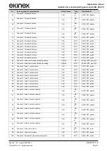
Page 27: ... representing the logic function output is sent on the bus on event of change alternatively a cyclic sending can be set The folder is enabled if General Logic functions enabled 9 1 Parameters and communication objects The folder is active if General Logic functions enabled Nome parametro Condizioni Valori Logic function disabled enabled Logic operation Logic Function enabled OR AND XOR XOR Delay a...

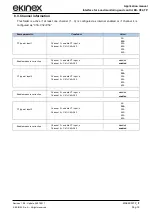
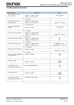
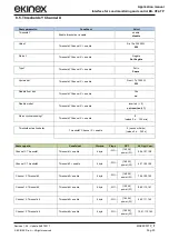
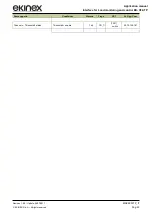
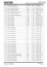
Page 28: ...r input change Nome oggetto Condizioni Dim Flags DPT N Ogg Com Logic Function X input 1 Logic Function X enabled Logic objet 1 enabled 1 Bit C W 1 001 switch 204 209 214 219 Logic Function X input 2 Logic Function X enabled Logic objet 2 enabled 1 Bit C W 1 001 switch 205 210 215 220 Logic Function X input 3 Logic Function X enabled Logic objet 3 enabled 1 Bit C W 1 001 switch 206 211 216 221 Logi...

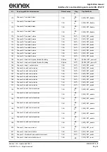
Page 29: ...PT_power W 13 Channel 1 Threshold 1 block 1 Bit WC U 1 003 DPT_Enable 14 Channel 1 Threshold 2 block 1 Bit WC U 1 003 DPT_Enable 15 Channel 1 Threshold 3 block 1 Bit WC U 1 003 DPT_Enable 16 Channel 1 Threshold 4 block 1 Bit WC U 1 003 DPT_Enable 17 Channel 1 Threshold 5 block 1 Bit WC U 1 003 DPT_Enable 18 Channel 1 Threshold 6 block 1 Bit WC U 1 003 DPT_Enable 19 Channel 1 Threshold 6 block 1 Bi...

Page 30: ...rol reset 1 Bit WC U 1 015 DPT_reset 48 Channel 1 Load control status 1 Bit R CT 1 001 DPT_switch 49 Channel 1 Threshold Load control status reset 1 Bit R CT 1 001 DPT_switch 50 Channel 1 Load control status reset 1 Bit WC U 1 015 DPT_reset 51 Channel 2 Instantaneous current mA 2 Bytes R CT 9 021 DPT_Value_Curr 52 Channel 2 Instantaneous power kW 4 Bytes R CT 14 056 DPT_power W 53 Channel 2 Instan...

Page 31: ...d control power threshold reading 4 Bytes R CT 14 056 DPT_power W 82 Channel 2 Load 1 control status 1 Bit R CT 1 001 DPT_switch 83 Channel 2 Load 2 control status 1 Bit R CT 1 001 DPT_switch 84 Channel 2 Load 3 control status 1 Bit R CT 1 001 DPT_switch 85 Channel 2 Load 4 control status 1 Bit R CT 1 001 DPT_switch 86 Channel 2 Load 5 control status 1 Bit R CT 1 001 DPT_switch 87 Channel 2 Load 6...

Page 32: ...hannel 3 Threshold 1 block 1 Bit WC U 1 003 DPT_Enable 116 Channel 3 Threshold 2 block 1 Bit WC U 1 003 DPT_Enable 117 Channel 3 Threshold 3 block 1 Bit WC U 1 003 DPT_Enable 118 Channel 3 Threshold 4 block 1 Bit WC U 1 003 DPT_Enable 119 Channel 3 Threshold 5 block 1 Bit WC U 1 003 DPT_Enable 120 Channel 3 Threshold 6 block 1 Bit WC U 1 003 DPT_Enable 121 Channel 3 Threshold 6 block 1 Bit WC U 1 ...

Page 33: ...status 1 Bit R CT 1 001 DPT_switch 151 Channel 3 Threshold Load control status reset 1 Bit WC U 1 005 DPT_alarm 152 Channel 3 Load control status reset 1 Bit R CT 1 001 DPT_switch 153 Channel 4 Instantaneous current mA 2 Bytes R CT 9 021 DPT_Value_Curr 154 Channel 4 Instantaneous power kW 4 Bytes R CT 14 056 DPT_power W 155 Channel 4 Instantaneous power W 2 Bytes R CT 9 024 DPT_power KW 155 Channe...

Page 34: ... W 184 Channel 4 Load 1 control status 1 Bit R CT 1 001 DPT_switch 185 Channel 4 Load 2 control status 1 Bit R CT 1 001 DPT_switch 186 Channel 4 Load 3 control status 1 Bit R CT 1 001 DPT_switch 187 Channel 4 Load 4 control status 1 Bit R CT 1 001 DPT_switch 188 Channel 4 Load 5 control status 1 Bit R CT 1 001 DPT_switch 189 Channel 4 Load 6 control status 1 Bit R CT 1 001 DPT_switch 190 Channel 4...

Page 35: ...tion 2 input 2 1 Bit WC U 1 001 DPT_switch 211 Logic Function 2 input 3 1 Bit WC U 1 001 DPT_switch 212 Logic Function 2 input 4 1 Bit WC U 1 001 DPT_switch 213 Logic Function 2 output 1 Bit R CT 1 001 DPT_switch 214 Logic Function 3 input 1 1 Bit WC U 1 001 DPT_switch 215 Logic Function 3 input 2 1 Bit WC U 1 001 DPT_switch 216 Logic Function 3 input 3 1 Bit WC U 1 001 DPT_switch 217 Logic Functi...

Page 36: ... di Comunicazione con ingresYes indipendenti Dimens DPT 1 bit 1 001 switch 2 bit 2 1 bit controlled 1 byte senza segno 4 character 5 8 bit unYesgned value 20 1 byte 1 byte percentuale 4 character 5 8 bit unYesgned value 20 1 byte 1 byte con segno 6 8 bit Yesgned value 2 bytes senza segno 7 2 byte unYesgned value 2 bytes con segno 8 2 byte Yesgned value 2 bytes virgola mobile 9 2 byte float value ...

Page 37: ...ekinex KNX defective devices must be returned to the manufacturer at the following address EKINEX S p A Via Novara 37 I 28010 Vaprio d Agogna NO Italy 11 1 Other information This application manual is aimed at installers system integrators and planners For further information on the product please contact the ekinex technical support at the e mail address support ekinex com or viYest the webYeste ...

Reviews: