3
The device has four operating modes with setpoint values
to be set independently for the operation in heating and
cooling. The setpoint values as well as the using during
the day of the various operating modes depend on a num-
ber of specific factors such as the building type, the use
of the room, the individual perception of heat and cold,
the ‘inertia characteristic of the room terminals, etc. and
should be carefully considered with the planner of the he-
ating system, the customer and the user.
Comfort
The comfort operating mode is generally set when people
occupy continuously a room.
Standby
The standby operating mode is set in case of absence
of short duration from the room. This mode provides a
small attenuation of the temperature compared to comfort
mode; the attenuation assumes a different direction de
-
pending on the seasonal mode setting (lower temperature
for heating, higher temperature for cooling).
Economy
The economy operating mode is set for example in case
of prolonged absence from the room, during the night
hours, etc. and provides an bigger attenuation of tempe-
rature larger than the standby mode.
Building protection
The building protection operating mode is provided with
a temperature threshold; when exceeded, warm or cold
conveying fluid is requested to the thermal generator to
avoid potential damages to the building (equipment, fur-
nishings, devices) caused by too low (frost protection) or
too high (overheating protection) internal temperatures.
The building protection function is effective only when the
thermal generator (boiler or chiller) is regularly operating.
If configured and connected to a window contact, the
device automatically switches to the building protection
mode at the window opening and switches back to the
previous mode at the window closing.
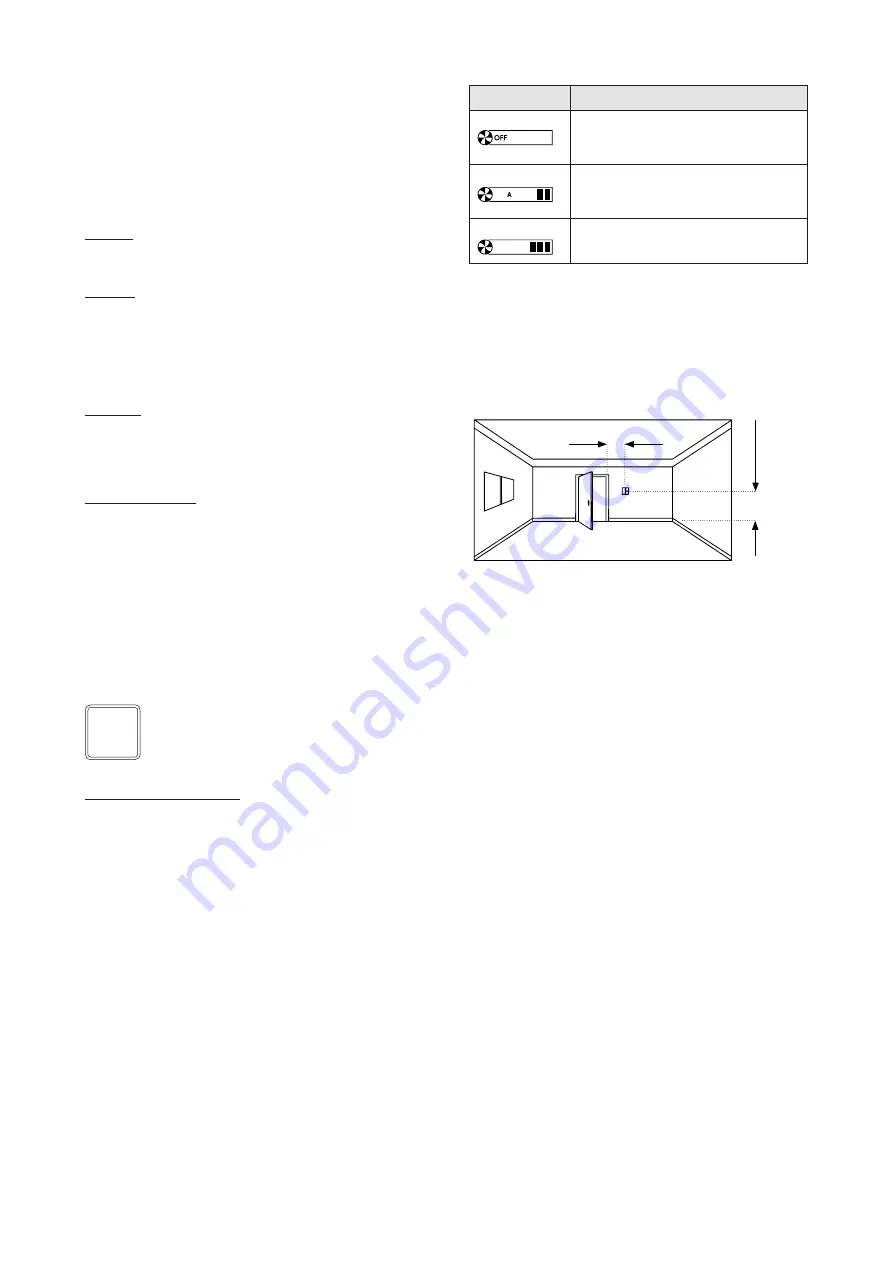
Mounting position
For the temperature control function the value of the room
temperature may be measured by the temperature sen-
sor integrated in the device, by another KNX temperature
sensor, by a temperature sensor connected to one input,
or be calculated as a weighted average value of two dif-
ferent sources.
Note. If the device is in the building protection
mode, when the temperature exceeds the threshold
setting, the valve of the hydraulic circuit is opened
even if the fan is switched off.
i
Symbol
Fan operation
Switched off mode (OFF): the fan is switched off
and the regulation can not activate it, indipendently
from the the difference between the measured tem-
perature and the current temperature setpoint.
Automatic mode (A): the fan speed is automatically
regulated depending on the difference between the
measured temperature and the current temperature
setpoint.
Manual mode: the fan speed is manually forced
to the level corresponding to the number of bars
switched on (from 1 to 5).
1,50 m
min 0,3 m
Changing operating mode
If the device is configured to operate as a slave, the set
-
ting of the operating mode is done via bus by another
KNX device with supervising function (such as a timer or
a centralised control and visualisation unit) of the building
automation system. The only change of operating mode
enabled manually is the recalling of the comfort mode
for a configurable time interval with ETS. If the device is
configured for stand-alone operation, the change of the
operating mode is done manually using the rockers for
the control of the room temperature controller functions.
Ventilation control
The device allow the control of the ventilation function.
The regulation may be continuous or stepwise (max 3
speed levels).
If the temperature value measured by the integrated sen-
sor is used, for an optimal temperature control the device
must be installed taking care of:
• installing the device on an inner wall of the room at a
height of about 1.5 m from the floor;
•
not shielding the device with curtains, furniture or other;
• verifying that from the duct connected to the wall box
does not come airflows that might affect the temperatu
-
re measurement;
• avoiding the installation close to heat sources (such as
domestic appliances or lighting devices), pipes for the
distribution of hot or cold water and terminal devices for
heating and cooling;
• avoiding the installation where the device may be
subject to direct sunlight through glass surfaces.
If these conditions can not be satisfied, it is appropriate to
use a weighted average value between two temperature
values measured in the same room according to the dif-
ferent possibilities offered from the device (temperature
sensor connected to an input or a KNX temperature sen-
sor). If a second temperature value can not be measured,
it is also possible to correct the value measured by the
sensor integrated in the device using the appropriate of-
fset parameter in the ETS application program.
Mounting
The device has degree of protection IP20, and is therefo-
re suitable for use in dry interior rooms. The installation of
the device requires the following steps:
a)
fix the metallic support (f) with the screws supplied (e)
on the wall box (g);
b)
if required, snap a square frame (d) of the form or flank
series, inserting it from the rear of the device (b) ;
c) connect the sensors or the contacts required to the
4-poles screw terminal block on the rear of the device;
d) insert the terminal for the bus (red/black), previously
connected to the bus cable, in its slot on the rear side


