4
(see also: “Connection of the KNX bus line”. At this
point it is recommended to carry out the commissio-
ning of the device (see also “Configuration and com
-
missioning”) or at least the download of the physical
address;
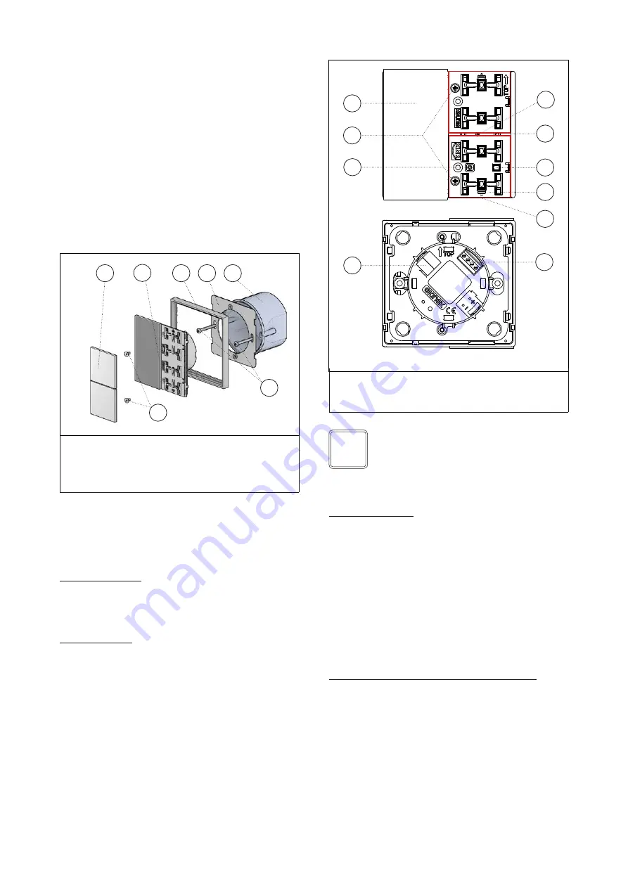
e) install the device (b) on the metallic support (f) throu-
gh the spring system, tightening then the two screws.
Mounting the device follow also the indication TOP (ar-
row tip pointing up) on the rear side of the device;
f) snap the two rockers (a) onto the device for the opera-
tion of the room temperature controller.
The device can only be mounted on a round or square
wall flush mounting box with 60 mm distance betwe
-
en fixing holes. If necessary, the metallic support for
mounting on the wall box can also be ordered separately
using the code EK-SMQ.
Switching and display elements
The device is equipped with a backlighted LC-display,
2 mechanisms for rockers mounting, 4 programmable
LEDs for each channel, a programming LED and a pro-
gramming pushbutton.
Switching elements
• Pushbutton (3) for switching between the normal and
programming operating modes
• Mechanisms (8) for room temperature control functions
to be completed with 2 square rockers
Display elements
• LC-display (1) with digits and symbols for displaying the
operating conditions of the device
• Red LED (4) for indication of the active operating mode
(on = programming, off = normal operation)
•
Eight freely programmable LEDs with lightguide (5);
e.g. as status feedback or as orientation nightlight
Measuring elements
The devices is provided with two sensors:
• temperature sensor (not visible, positioned behind the
passage 7);
• relative humidity sensor (6).
Temperature sensor
The integrated temperature sensor measures the tempe-
rature value in a range from 0 °C to +40 °C with a re
-
solution of 0.1 K. The measured value can be corrected
by the environmental influences by means of an offset
parameter. In order to avoid that too rapid temperature
fluctuations negatively affect the regulation process, an
acquisition filter can be set. If necessary, for the regula
-
tion can be used a weighted average between the value
measured by the integrated sensor and another tempera-
ture value measured in the room by a temperature sensor
connected to one of the inputs of the device or received
via bus by another KNX device. The value measured by
the sensor can be sent on the bus.
Relative humidity sensor (only for EK-EQ2-TP-...)
The measurement of the relative humidity of the room air
mass significantly extends the functions of thermal regu
-
lation and allows to increase comfort and safety of ope-
ration. In combination with the HVAC system, the device
allows to perform a real building climatic control indepen-
dently for each room or zone, adding to heating and co-
oling of the possibility of controlling the dehumidification
and humidification of the rooms. The value measured by
the sensor can be sent on the bus..
Note. Programming pushbutton and LED are ac-
cessible from the front side of the device. The de-
vice addressing may be easily carried out after the
assembly of the frame, removing the rockers. Once
the addressing has been carried out, the device
configuration can be later downloaded without pres-
sing the programming pushbutton.
i
a
b
d
f
g
e
a) Square rockers 40x40 mm (to be ordered separately)
b) Device
c)
Screws for fixing the device on the support
d)
Frame of form or flank series (to be ordered separately)
e)
Screws for fixing the support on the wall box
f) Mounting support for wall box
g) Wall box (not delivered by SBS)
c
ESEKEQ2TP
1) LC-display
2) Fixing screws for support
3) Programming pushbutton
4) Programming LED
5) Lightguide for rockers LED
1
2
4
3
6
7
5
6) Relative humidity sensor
7) Temperature sensor
8) Mechanisms for rockers’ mounting
9) Terminal for bus line connection
10) Terminals for input connection
9
8
10
DCEKEQ2TP


