3
INSTALLATION TECHNICAL NOTES
• Installation and maintenance must be
performed only if the power supply has
been turned off.
• Installation and maintenance must only
be performed by qualified personnel in
compliance with current regulations.
• The product must be installed insi-
de an electrical panel protected against
overvoltages.
• The product must be installed in a verti-
cal position with the front / label facing
the front or in a horizontal position with
the front / label facing upwards. Other
product installation positions are not al-
lowed. The bottom position with the front
panel / label facing down is not allowed.
• Keep separated the circuits at 230V (LV)
and the circuits not SELV from circuits
to low voltage (SELV) and from any con-
nection with this product. It is absolutely
forbidden to connect, for any reason
whatsoever, directly or indirectly, the
230V mains voltage to the bus or to other
parts of the circuit.
!
Setup and installation
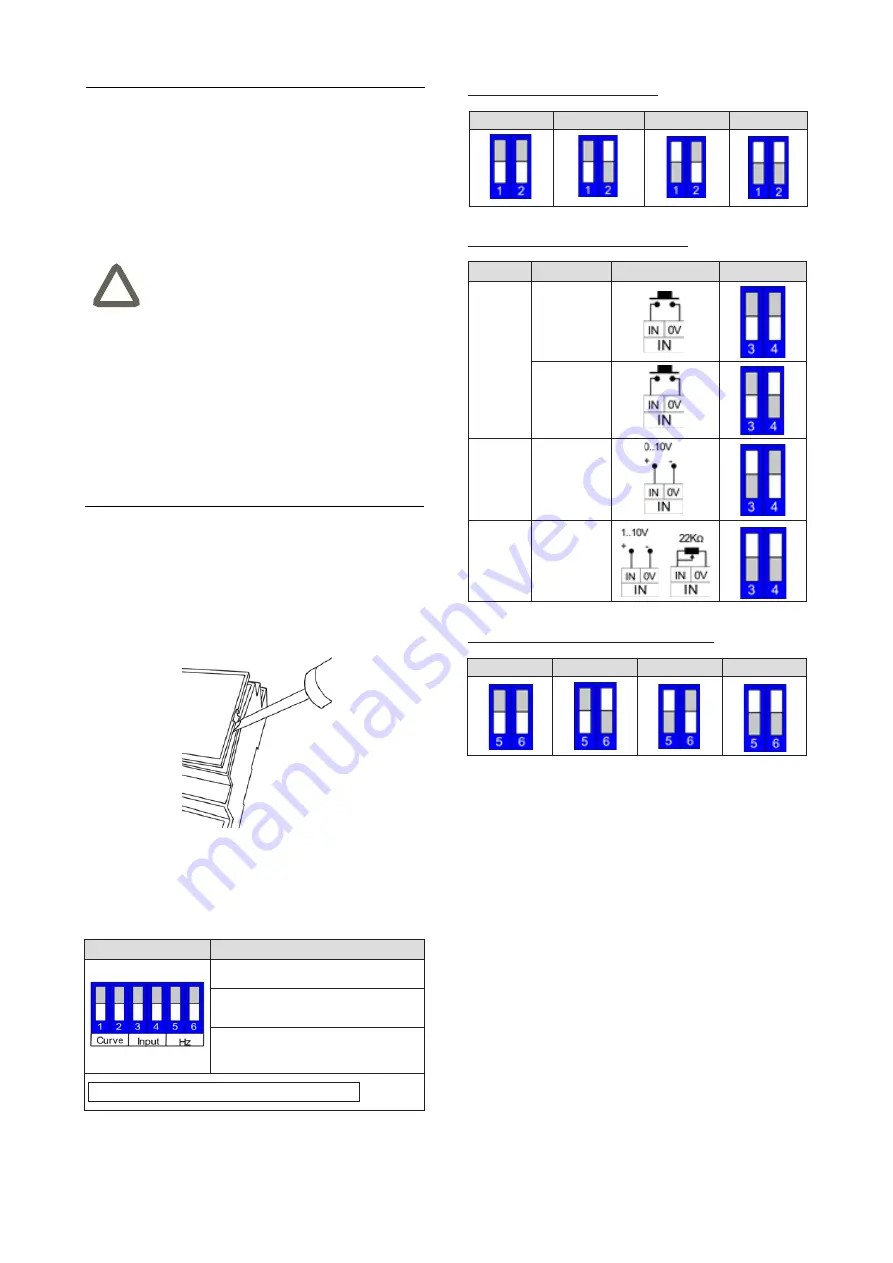
In order to setup the dip-switch, it is necessary to open
the device front cover, by means of a screwdriver as de-
tailed in the image below.
Configuration
Settings
Switch 1-2 = dimming curve
Switch 3-4 = input type
Switch 5-6 = Output Frame Rate –
Frequency
Note: Factory settings = ALL OFF
Switches 1-2 (dimming curve settings)
Default
Exponential
Quadratic
Linear
Switches 3-4 (input local command settings)
Command
Description
Connection
Configuration
Pushbutton
N.O. pushbutton
without memory
N.O. pushbutton
with memory
0 - 10 V
Analog input
0-10V
1 - 10 V
Analog input
1-10V
or
Potentiometer
Switches 5-6 (output dimming frequency settings)
300 Hz
600 Hz
1200 Hz
Reserved
DALI bus line and command connections
The connection to the DALI bus network and the local
commands is done via the screw terminal, located on the
front of the device in the upper part.
The length of the connection cables between the local
commands (N.O. Pushbutton, 0-10V, 1-10V, Potentiome-
ter or other) and the product must be less than 10m; the
cables must be dimensioned correctly and they should be
isolated from every wiring or parts at voltage not SELV.
Use double insulated shielded and twisted cables.
The length and type of the connection cables to the DALI
bus must be compliant with the protocol specification and
with the present regulations and they should be isolated
from every wiring or parts at voltage not SELV. Use dou-
ble insulated shielded and twisted cables.
All the devices and the control signal connected to the
DALI bus and to the local command (N.O. Pushbutton,
0-10V, 1-10V, Potentiometer or other) must be SELV (the
devices connected must be SELV or supply a SELV si-
gnal).
The 6-way dip-switch setting (under the front cover) offers
a wide choice of possible configurations.


