FITTING THE DECORATIVE FRAME ASSEMBLY
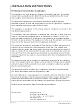
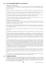
Eko 5010, Eko 5020 and Eko 5030 Models :
Remove the decorative frame assembly
from any protective packaging, and remove
any protective film that may be present on
the frame.
The frame is hung onto the firebox via the
two upper hanging brackets and then
secured to the firebox via the two lower
knurled fixing bolts, which are inserted
through the holes in the lower frame
mounting brackets after the frame is in
position. See figures 8 and 9
.
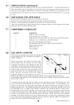
Eko 5040 Models :
Remove the glass facia panel from any pro-
tective packaging. The glass facia panel is
supported by four M6 screws which pro-
trude from the front of the outer casing.
Ensure each
screw is
u n s c r e w e d
approximate-
ly one turn
from the
fully screwed
in position in
order to cre-
ate a 2mm gap (shown in figure 10).
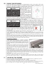
Simply hang the facia panel onto the outer
casing (figure 12) ensuring that the corre-
sponding keyhole shaped holes engage the
screwheads fully.
To fit the decorative corner columns, ensure the main glass facia is mounted in position. Remove any tran-
sit tape and unscrew the front clamping disc and remove.
Compress the column assembly and position behind the glass panel, lining up with the appropriate hole (as
shown in figure 11). Release the assembly when in position and secure in place by refitting the front clamp-
ing disc.
7
8.4
Eko 5010, Eko 5020 and Eko 5030 Models
Eko 5040 Models
2mm
Compress
the assembly
Front clamping disc
Figure 9
Figure 8
Figure 10
Figure 12
Figure 11
©
2009 Focal Point Fires plc.


