background image

VENTILATION (continued)

Any ventilation fitted must comply with BS 5871 part 4 and BS 5440 part 2.  Ventilation fitted under, or

within immediate vicinity of the appliance must not be used as it may adversely effect performance of the

ODS system. The appliance MUST NOT be installed in a bedroom, bathroom or any sleeping area. For

Republic of Ireland, see relevant rules in force.  The appliance should not be installed within 1 metre of any

air vent.

UNPACKING THE APPLIANCE

Remove the outer packaging, remove any instructions or fixing kits. 

Read ALL these instructions before continuing to unpack or install this appliance.

Lift off the remaining packaging components and remove the contents of the box.

Check that the components supplied correlate with the component checklist.  Please dispose of all the pack-

aging materials at your local recycling centre.

COMPONENT CHECKLIST

QUANTITY

DESCRIPTION

1

Firebox and burner assembly

Set of manufacturers instructions

1

Decorative frame assembly (Eko 5010, Eko 5020 and Eko 5030 models)

1

Decorative trim set (Eko 5020 and Eko 5030 models)

1

Glass facia assembly (Eko 5040 models)

4

Spring loaded decorative corner columns (Eko 5040 models)

1

Screw and wall plug pack

1

Rubber grommet

1

Fitting template

GAS SUPPLY ROUTES 

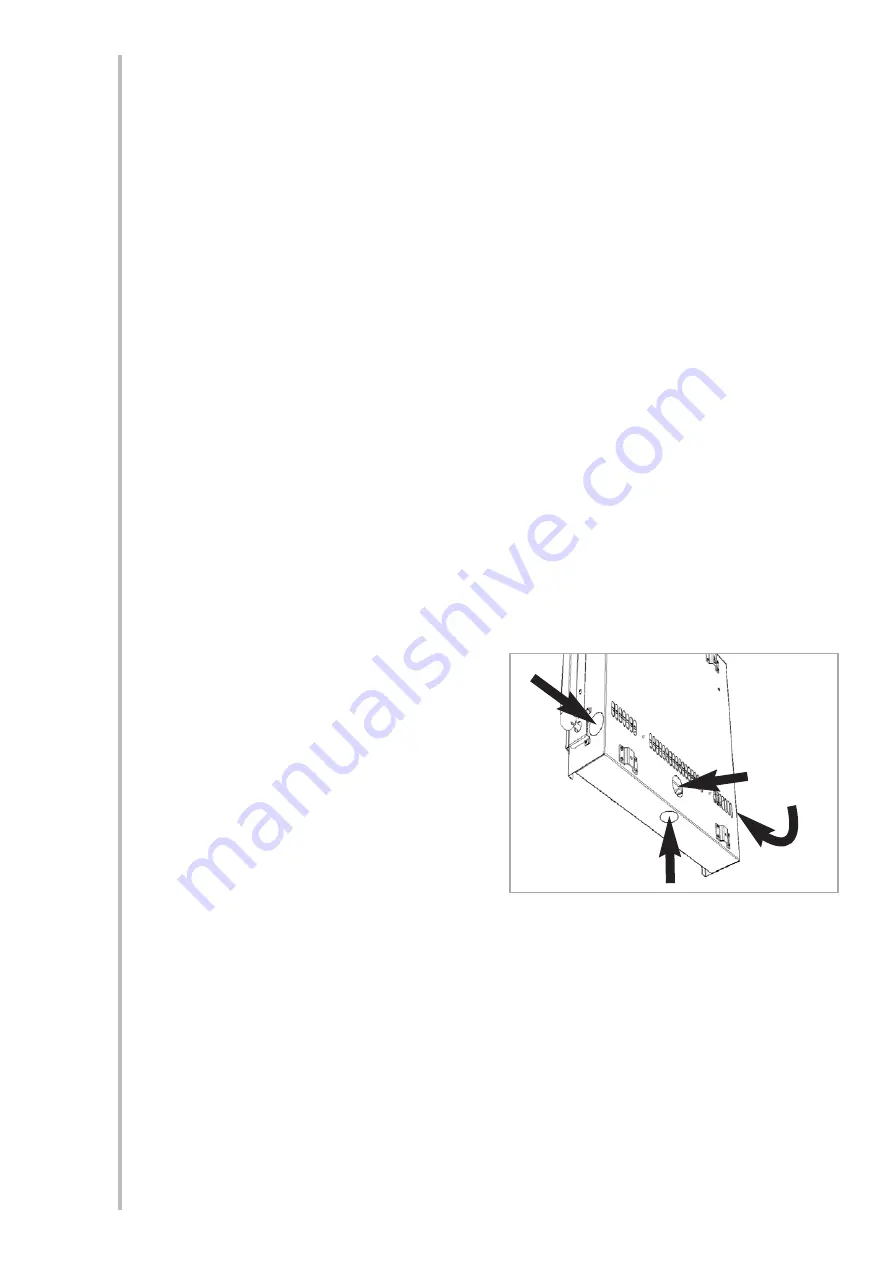
There are four possible entry points for the gas
supply pipework to enter the appliance firebox as
shown in figure 2.

These entry points are ‘knock out’ type holes.
Non-concealed gas connections may be made
using the entry points in the bottom or sides of
the firebox. A concealed gas connection may be
made using the knock out hole in the centre back
of the firebox. Select the most appropriate entry
point and knock out the relevant hole with a
sharp tap from a hammer and fit the rubber
grommet supplied. A small incision can now be
made in the rubber to slip snugly around the outside of the supply pipe and sleeving.

All installation pipework must be in accordance with the current edition of National regulations/codes
and the rules in force.

In order to avoid unnecessary pressure drops, use of small diameter pipe should be kept to a mini-
mum, for example, we recommend no more than 1.5 metres of 8mm pipe.  If a concealed gas con-
nection is to be made, the supply pipe should always be sleeved through walls and floors using the
shortest possible route. For concealed supply pipe routing, pipes must (where possible) be vertical
and providing there is sufficient wall thickness available, they should be placed in pipe chases.
Horizontal pipe runs should be avoided.  Prior to chasing a solid wall, an inspection should be made
to note the proximity of any cables/sockets outlets which may already be buried.  Pipes must be
secured using suitable clips and protected against corrosion. Ideally factory finished protected
pipework and fittings should be used. Joints should be kept to a minimum and compression fittings
must not be used. The pipework installation must be tested for tightness before any protection is
applied and/or the pipework and fittings are buried. 

4

5.0

5.1

6.0

4.1

©

2009 Focal Point Fires plc.

Figure 2

Summary of Contents for eko 5010

Page 1: ...user instructions All instructions must be handed to user for safekeeping Revision A 06 09 Country s of destination GB IE eko 5010 eko 5020 eko 5030 eko 5040 fuel effect gas fire manual remote contro...

Page 2: ...Eko 5010 Eko 5020 Eko 5030 Eko 5040 2009 Focal Point Fires plc...

Page 3: ...convert from cubic feet ft3 to cubic metres m3 divide the room vol ume in ft3 by 35 3 This appliance is intended as a secondary source of heat only and should not be used in a room without some form...

Page 4: ...background heat ing present If the appliance is used in a room as the sole source of heat then condensation may occur on colder surfaces within the room On first light up of a new appliance burning o...

Page 5: ...om size in cubic metres m3 divide the room volume in cubic feet ft3 by 35 3 SITE REQUIREMENTS This appliance is designed to be wall hung Do not recess any part of the appliance into the wall This appl...

Page 6: ...s should be positioned on the wall above the appliance It should be established that any mirrors or picture frames etc to be positioned on the wall above the appliance are able to withstand prolonged...

Page 7: ...connections may be made using the entry points in the bottom or sides of the firebox A concealed gas connection may be made using the knock out hole in the centre back of the firebox Select the most...

Page 8: ...For further guidance for wall fixing in tim ber framed buildings refer to any relevant local codes of practice Flat Wall Fixing All Models To assist with fixing the appliance a template is provided a...

Page 9: ...spark There should be no need to adjust this If under any circumstances the piezo electric spark fails the pilot cannot be lit manually SETTING PRESSURE The pressure test point is located on the left...

Page 10: ...g Ensure each screw is u n s c r e w e d approximate ly one turn from the fully screwed in position in order to cre ate a 2mm gap shown in figure 10 Simply hang the facia panel onto the outer casing f...

Page 11: ...13 Check the purpose provided ventilation is un obstructed 14 Light the fire and test setting pressures 15 Check safe operation of the appliance For specific servicing instructions see relevant sectio...

Page 12: ...noting the units in which the values are expressed Most analysers display carbon dioxide CO2 con centrations in percentage terms and carbon monoxide concentration in parts per million ppm terms In ord...

Page 13: ...as a hole holes through which there is a draft Fire is too close the an air vent Fire is sited on disused chimney breast which has not been adequately sealed up Dirt or lint in pilot aeration hole or...

Page 14: ...als or flooring should protrude onto the hearth if fitted This appliance incorporates a combustion monitoring system ODS DO NOT burn any foreign material on this fire Under no circumstances shall the...

Page 15: ...local Codes and or Regulations Ventilation fitted under or within immediate vicinity of the appliance must not be used as it may adverse ly effect performance of the combustion monitoring system ODS...

Page 16: ...ass cleaner Test on a small area first PAINTED AREAS These can be cleaned using a dry cloth STAINLESS STEEL AREAS These can either be cleaned using a proprietary stainless steel metal cleaner or baby...

Reviews: