DK50 2V/50
DK50 4VR/50
03/2013
- 11 -
NP-DK50 2V50-4VR50-5_03-2013.doc
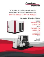
Fig.7
1
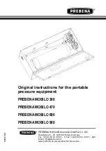
Fig.8
Dental compressor DK50 2V/50, DK50 2V/50/M, DK50 4VR/50, DK50 4VR/50/M
(Fig.5)
After removing all packaging material, place the product on the floor and remove stabilization parts Y (Detail
A). Connect output hose with end-piece to the appliance. Plug the mains cord plug into a socket.
Dental compressor in box DK50 2V/50S, DK50 4VR/50S
(Fig.4, Fig.5)
After unpacking, place the product onto the floor in a room, release it from packaging materials and remove
fixation parts (Y) - detail A. Place a wall end stop (32) 2 pcs on compressor casing in the rear, upper part of
the casing and fit in the casing on the required place.The end-stops shall ensure the sufficient distance of the
casing from the wall for thorough ventilation. For fitting the compressor in the place to the casing it is
necessary to disassemble the casing door and take off the connecting reinforcement (29) in the front bottom
part of the casing. Protrude the pressure hose under the casing and fix it to the appliance in a suitable
manner. Grasp the compressor at its handle and using the transport mechanism (30) and the built-in
castors (31) place it to the casing. Embed the hose (27) of manometer (25) of the casing to fast-on coupling
on the compressor, place back the connecting reinforcement (29) and connect output pressure hose to the
compressor.
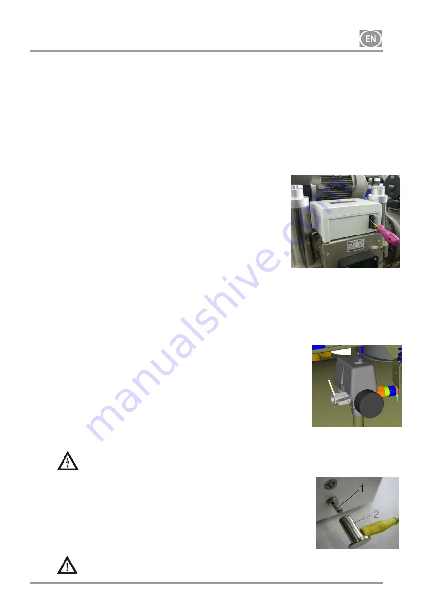
Connect the connector (26) of casing to the compressor and
connect the electric mains plug to mains socket.
In case of disassembling the compressor it is necessary to
disconnect the connector of soundproofing box by using the
screwdriver.
(
Fig.6)
Dental compressor in DK50 2V/50S/M, DK50 4VR/50S/M
(Fig.4, Fig.5)
After removing all packaging material, place the product on the floor and remove stabilization parts Y (Detail
A). Place the compressor into housing similarly as in the previous paragraph. Prior to placing the
compressor into housing, protrude house for condensate drain via hole in housing and connect it to a bottle
(20). Magnetic holder (28) with a vessel (20), for entrapping the condensate from the dryer may be fitted
onto any vertical part of casing, or from front on its door. When fixing the holder with a vessel at the housing
side it is necessary to consider a space of at least 11 cm between the housing and furniture. Distance
smaller than the specified one may cause problem with handling of the vessel.
9.2.
Compressed air outlet
(Fig.7)
Lead the pressure hose from the output of compressed air (1) to the
appliance – dental set.
9.3.
Electrical connection
Plug the electrical cord into the mains.
The appliance is equipped with a grounded plug. Make sure this connection complies
with local electrical codes. The mains voltage and frequency must comply with the data
stated on the appliance label.
(Fig.8)
Keep the socket easily accessible to ensure that in an emergency the
appliance can be safely disconnected from the mains.
Connection to the power distribution box must be max.16 A.
The connection of the earth ground pin
6mm (1) with other
appliances must be completed in accordance with local electrical
codes. The female socket (2), which is not included in the standard
set, is an optional accessory.
Electrical cable may not contact the hot parts of a compressor. Insulation could be
damaged!
If any electrical cord or air hose is damaged it must be replaced immediately.
Fig.6
Summary of Contents for DK50 2V/50
Page 1: ......
Page 2: ......
Page 3: ...CONTENTS 3 INHALT 20 38 OBSAH 57 Ed 5...
Page 22: ......
Page 43: ...DK50 2V 50 DK50 4VR 50 03 2013 41 NP DK50 2V50 4VR50 5_03 2013 doc 1 CE CE 93 42 EEC 2 2 1 2 2...
Page 44: ...DK50 2V 50 DK50 4VR 50 NP DK50 2V50 4VR50 5_03 2013 doc 42 03 2013 2 3 3 CE...
Page 49: ...DK50 2V 50 DK50 4VR 50 03 2013 47 NP DK50 2V50 4VR50 5_03 2013 doc 4 8 5 C 40 C 70 5 9...
Page 61: ...DK50 2V 50 DK50 4VR 50 03 2013 59 NP DK50 2V50 4VR50 5_03 2013 doc O...
Page 84: ......


