background image

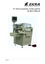
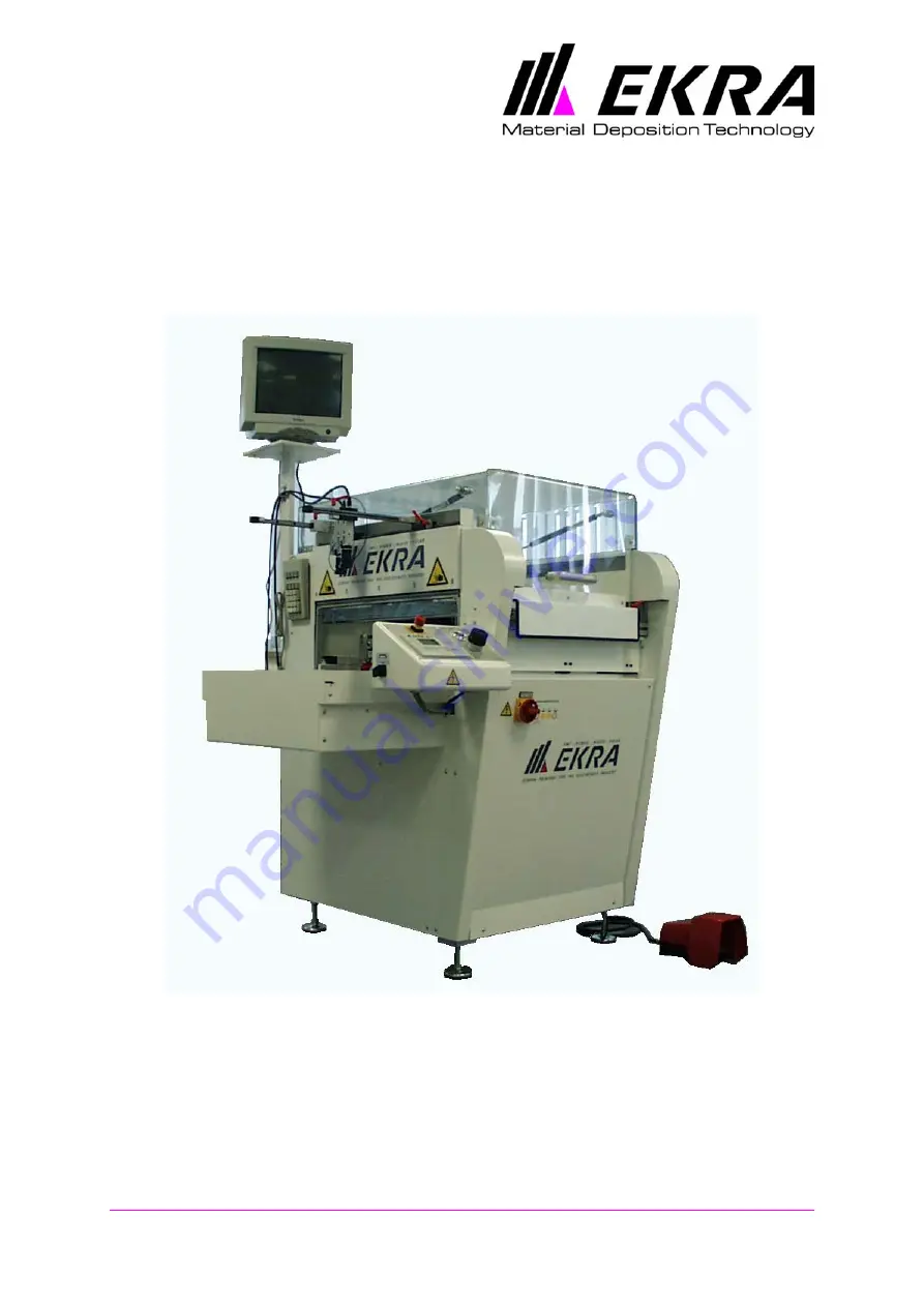
E1 Semi-automatic screen printer

System Manual

30.8.02

Summary of Contents for E1

Page 1: ...E1 Semi automatic screen printer System Manual 30 8 02 ...

Page 2: ...No part of this manual may be reproduced duplicated or translated In this manual usually no mention is made of any existing patents utility model rights or trademark rights applicable to any products The absence of such mention gives no grounds to assume that no proprietary rights are attached to such products ...

Page 3: ...392 EEC Appendix IIA of June 14 1989 EC Machine Directive 91 368 EEC of June 20 1991 EC Low Voltage Directive 73 23 EEC Electromagnetic Compatibility 89 336 EEC applied harmonized standards DIN EN 292 Part 1 and Part 2 safety of machines devices and systems DIN EN 29001 ISO 9001 quality standards DIN EN 60204 Part 1 electrical equipment of machines applied national standards and technical specific...

Page 4: ...sonnel 1 6 Possible hazards when operating the machine 1 7 Proper use 1 7 Warranty and liability 1 8 Safety regulations 1 9 Organisational measures 1 9 Safety devices 1 9 Emergency stop switches 1 9 Safety switches and locks 1 9 Using safety devices 1 10 Bypassing the locks 1 11 Checking safety devices 1 11 Informal safety measures 1 12 Training of personnel 1 12 Machine control 1 12 Safety measur...

Page 5: ...4 Print area with cover open 3 5 Printing table 3 6 Squeegee unit 3 7 Control desk 3 8 Functional description of the operating elements 3 9 Control panel 3 9 Signal lamps 3 9 Function keys 3 9 Main menu display 3 10 Cursor keys 3 11 File menu display 3 11 Technical data 3 12 4 Switching On and Off 4 1 Switching on 4 1 Switching off 4 2 Emergency stop 4 2 Switching on after an emergency stop 4 2 5 ...

Page 6: ...7 1 8 Electrical and Pneumatic Equipment 8 1 Electrical equipment 8 1 Control cabinet 8 1 Control desk 8 1 Snap off control 8 2 Cleaning flap 8 2 Snap off control 8 3 Cover safety switch 8 3 Table drive motor view from rear 8 4 Table loading position sensors 8 4 Squeegee position sensor 8 5 Squeegee motor 8 5 Pneumatic equipment 8 6 Printing nest 8 6 Service unit and pressure adjustment 8 6 Squeeg...

Page 7: ... 8 02 Page E1 Semi automatic screen printer System Manual Pneumatic service unit 9 3 Casing 9 3 PC positioning system MOPS 9 4 Bearings and guideways 9 4 10 Vendor Documentation 10 1 Ordering spare parts 10 1 Vendor documentation 10 2 Declaration of Trained Personnel ...

Page 8: ...ioning the machine you should read the user s manual thoroughly even if you have attended a training course explaining how to operate the machine Sign the last page to verify that you have fully read and understood the user s manual The owner of the machine is only permitted to authorise personnel who satisfy this requirement to operate and maintain the machine Safety and accident prevention All E...

Page 9: ...easures to be taken to prevent injuries Chapter 3 Description of the Machine describes the main components of the machine and provides an overview of the options and their function application Chapter 4 Switching On and Off explains how to switch on switch off and start the printer Chapter 5 Operation explains the procedures used for operating the E1 semi automatic printer Chapter 6 Manual Optical...

Page 10: ...otentially fatal may be detrimen tal to health or may cause serious injury The potential hazards are explained in Chapter 2 Safety Hazards Terminology The following terms and abbreviations are used in the user s manual Print material Parts that are to be printed Printing medium Paste solder silicone or other materials which are applied to the part to be printed Coating flooding Application of the ...

Page 11: ... surrounding environment The entire shipment must be stored in a dry and where possible and nec essary heated room The shipment must never be stored outdoors Pro tection against rain or intensive sunlight must also be provided When taking delivery of the machine unload the crates and check that no components are missing Transport commissioning repairs Transport Note The machine weighs approximatel...

Page 12: ...ried out by the owner during the warranty period If problems or faults occur which you cannot rectify yourself and which are not described in this user s manual please contact the EKRA Service Hot line Telephone 49 0 7143 8844 0 Switchboard 49 0 7143 8844 72 Service Dept Service Dept Please make a note of the following details before calling Ekra Note You can obtain further contact addresses from ...

Page 13: ...s and regulations applicable for the installation location must also be observed Obligations of the owner The owner must ensure that the machine is operated only by personnel who are familiar with the basic occupational safety and accident pre vention regulations and trained to use the machine who have read and understood the chapter on safety and the warnings in this user s manual and have verifi...

Page 14: ...machine should only be used for its intended purpose if it is in perfect working order Faults which may have a detrimental effect on safety must be rectified immediately Proper use The E1 semi automatic printer is intended for printing printable SMT mate rials solder paste SMD adhesive The machine can also be used for printing hybrid and solar cell media Any other use deviating from the machine s ...

Page 15: ...ranty claims Warranty and liability claims for injury and damage shall be excluded if they are due to one or more of the following Incorrect use of the machine Incorrect assembly commissioning operation and maintenance of the machine Operation of the machine with faulty safety devices or incorrectly attached or non functional safety and protective devices Failure to observe the information in the ...

Page 16: ...tic printer is equipped with the following safety devices Emergency stop switches Emergency stop switches interrupt the supply of power to the printer An emergency stop switch is fitted It is located at the front on the left hand side of the printer frame Safety switches and locks The E1 semi automatic printer uses hardware and software safety switches to prevent injuries caused by printer compone...

Page 17: ... of the machine below the cover is a cleaning flap The flap is monitored by a safety switch Opening the cleaning flap during a printing process triggers an emergency stop A safety screen is fitted at the inlet to the printing table The safety screen is safeguarded by a hardware safety switch It pro tects the operator from reaching into the print area from the outside If the screen is moved an emer...

Page 18: ...the machine or system is started Safety devices may only be removed if the machine is at rest and service work is to be carried out and if measures have been taken to ensure that the machine cannot be started inadvertently Checking safety devices Cover Start the machine while the cover is open The E1 printer should not start Open the cover during a printing cycle An emergency stop must be triggere...

Page 19: ...ucted personnel are permitted to operate the machine Responsibilities for assembly commissioning operation set up main tenance and repair must be divided up and assigned accordingly Trainee personnel are only permitted to operate the machine under supervision of an experienced person Machine control Never make program modifications to the software Safety measures under normal operating conditions ...

Page 20: ...nd repair troubleshooting The intervals specified for the prescribed maintenance and repair work must be observed The operating personnel must be informed before any maintenance and repair work is started Before commencing maintenance inspection and repair work care must be taken to ensure that the machine is de energised and that the main switch cannot be switched on again inadvertently A warning...

Page 21: ...ies to lubricants adhesives and solder pastes Solder pastes and adhesives which can no longer be used must be returned to the manufacturer Lubricants and residues of pastes and creams must be disposed of as hazardous waste If pastes or adhesives containing solvents are used the owner of the E1 printer must ensure that sufficient ventilation is provided Further more the concentration of vapours con...

Page 22: ...maintenance work on the machine The printer must not be operated if the safety devices are not func tioning correctly Do not wear any loose fitting clothing when working with the E1 printer Before commissioning the E1 printer check whether there are any tools or damaged or loose parts which could prevent mechanical movement of the machine and thus cause damage Always wear protective gloves when ha...

Page 23: ...ency stop switch An emergency stop switch is fitted on the front left hand side of the E1 semi automatic printer Pressing the emergency stop switch interrupts the supply of power The emergency stop switch should only be pressed in emergencies The emergency stop switch must be released before the machine is restarted Emergency Main switch Cover Safety switch on outside of cover at rear Safety switc...

Page 24: ...n A safety screen is fitted at the inlet to the printing table The safety screen is safeguarded by a hardware safety switch It protects the operator from reaching into the print area from the outside If the safety screen is moved an emergency stop is triggered Checking safety devices Cover Start the machine while the cover is open The E1 printer should not start Open the cover during a printing cy...

Page 25: ...ersonnel provided that the machine is operated correctly Operating personnel should be aware of the following hazards Fig 2 Warning labels Danger The operator must take special care when the printing table is mov ing Failure to do so could result in hand injuries if the operator reaches into the area containing moving parts Preventive measures The operator should only reach into the area containin...

Page 26: ...e solder paste in open containers and do not leave solder paste residue in the printer if it is not being used Always make sure that sufficient vapour extraction is provided Do not touch mucous membranes with contaminated hands Other hazards Danger Solder paste is a tin lead alloy with a rosin based fluxing agent Birth defects are possible if pregnant women who come into contact with solder contai...

Page 27: ... in the fine pitch range Printing sequence The operator sets up the printing stencil in the machine by hand Two clamping cylinders fix the stencil in position in the guideway The snap off is adjusted by hand using a handwheel on the right hand side of the machine The value is indicated by a high precision indicating instru ment The operator adjusts the squeegee pressure with the pressure regulator...

Page 28: ...ine components Front of machine Fig 3 Front of machine 1 Main switch 7 MOPS cameras 2 Cleaning flap 8 Keypad 3 Snap off and pneumatic settings on right hand side 9 Emergency stop switch 4 Protective cover 10 Control desk 5 Print area 11 Printing table guideway 6 Screen for manual optical positioning sys tem MOPS 12 Foot switch 4 10 9 8 7 6 5 3 2 1 11 12 ...

Page 29: ...luding the machine control unit is located behind the front panel This is fixed in place with four screws PC positioning system MOPS Fig 5 PC positioning system rear of machine 1 Frequency converter printing table drive 3 Ballast module delay printing table 2 Changeover squeegee drive snap off 4 Motor control squeegee drive snap off 2 4 1 3 Valve terminal PC with MOPS image processing Cable feed t...

Page 30: ... setting Pneumatic setting Fig 7 Pneumatic control unit Snap off Handwheel indication One rotation of the outer indicator corresponds to 1 mm snap off To reduce snap off turn handwheel clockwise To increase snap off turn handwheel anti clockwise Pressure gauge film tensioning frame Pressure gauge screen clamping Pressure gauge main operating pressure Service unit ...

Page 31: ...for the screen frame are adjustable Release the levers at the front and rear and adjust the position of both guideways Once the screen fits perfectly in the guideways lock all levers To clamp the behind actuate the screen clamping switch The clamping cylinders are pressurised and clamp the screen in place Note Always align the screen layout centrally 1 Locking lever stencil guideway 5 Squeegee hea...

Page 32: ... printing cycle Then align the PCB with the printed image on the film by adjusting the printing table manually The PCB is fixed in the printing nest optionally with vacuum suction with the clamping rails 1 Control desk 7 Table adjustment in X direction 2 Clamping strips PCB holder 8 Table adjustment in Y direction 3 PCB support 9 Table adjustment in X direction 4 MOPS cameras 10 PCB clamping switc...

Page 33: ... precision guided pneumatic cylinders for each unit execute the squeegee stroke The down stop can be adjusted using the down stop micrometers The pivoting range of the individual squeegees can be limited mechanically by adjusting the pivot stop screws To allow cleaning of the screen the cleaning flap can be opened forwards enabling the underside of the screen to be cleaned Note If the screen is re...

Page 34: ...12 PCB clamping The switch for PCB clamping has three positions O AUTO and I AUTO In this position the foot switch is used for clamping the PCB When the foot switch is released the printing table moves to the printing position The printing cycle is executed and the printing table moves away from the printing position again The PCB clamping is released automatically I Set the switch to the I positi...

Page 35: ...his lamp showing a green light indicates that the printer is in oper ation ERROR This lamp showing a red light indicates that an error has occurred Function keys The ON button switches the control voltage on The OFF button switches the control voltage off Up press this button to move up through the main menu on the display Down press this button to move down through the main menu on the display E ...

Page 36: ...to printing position Print forwards Printing table moves to loading position Note The SQUEEGEE STOP FRONT function can only be used with printing mode 1 Stop Press this button to stop the squeegee Main menu display The name of the program is shown in the header of the main menu This is the program that has been chosen for the printing process You can use the function keys in the main menu to chang...

Page 37: ...ey Press this button to select the letters in descending order Confirm the letter that you want to select by pressing the Enter key Press this button to select the file menu To return to the main menu press this button again File menu display In the file menu you can save the currently active program load a different program from the files available for selection or delete an existing pro gram Ent...

Page 38: ... Two independent pneumatic printing heads closed loop control circuit squeegee free swinging Squeegee pressure 0 4 bar equivalent to 0 320 N adjustable via pneumatic cylinders Squeegee types all types Squeegee speed min 5 mm s max 100 mm s Squeegee depth setting down stop adjustable on squeegee head Separation speed 0 4 1 mm per second Separation way 2 mm Snap off setting manually with handwheel 1...

Page 39: ...ion Anywhere in area of PCB Performance Generation of a program 5 min Product changeover 5 min Machine control Hardware Microprocessor controlled LCD display Memory 100 PCB profiles General data Electrical connection 230 V 50 Hz 1 kW Pneumatic connection 6 10 bar Width x depth x height 1270 mm x 1100 mm x 1420 Working height 850 mm 25 mm adjustable Weight 350 kg Permissible operating temperature 1...

Page 40: ...ng message appears The OK and RUN LEDs light up green Press the button on the control panel The control voltage for the screen printer is switched on The following message appears on the display PRESS FOOT SWITCH Press the foot switch The following message appears on the display REFERENCE DRIVE RUNNING The screen printer performs a reference drive The main menu appears on the display The screen pr...

Page 41: ...ions where people could be injured or parts of the printer could be damaged or destroyed Strike the red button of the emergency stop switch with your hand The power supply to the screen printer is interrupted All moving parts are brought to a standstill Switching on after an emergency stop Release the emergency stop switch by turning the red button clock wise Press the button on the control panel ...

Page 42: ...side of the machine Set the main pneumatic connection to 5 to 6 bar on the pressure gauge Set the screen clamping to 3 to 4 bar Set the compressed air for the film tensioning frame to 1 to 2 bar On the control desk Set the squeegee pressure 0 to 4 bar 1 bar is equivalent to 80 new tons Note It may be the case that different settings produce better results for your application Note Refer also to Ch...

Page 43: ...the PCB and the clamping strip Tighten the two fixing screws holding the clamping strips at the front and rear In the printing nest position the magnetic strips or magnetic pins to support the PCB Place the PCB in the printing nest Make sure that the PCB is lying flat and that it can be clamped Turn the PCB clamping switch at the side of the control desk to the I position The PCB is clamped Note I...

Page 44: ...er edge of the stencil guideway If it is lower the table by turning the snap off handwheel Turn the screen clamping switch to the 0 position OFF Release the levers on the stencil guideway Push the stencil into the stencil guideway towards the rear to the stop position the print layout centrally Adjust the position of the stencil until the PCB layout and the stencil lay out are fully aligned Close ...

Page 45: ...two keys until the parameter value is set in mm sec 10 110 mm sec Confirm entry of the parameter by pressing ENTER Press the key and select the SQUEEGEE POSITION REAR parameter Press either of these two keys until the rear squeegee position is set in mm 0 550 mm Confirm entry of the parameter by pressing ENTER Press the key and select the SQUEEGEE POSITION FRONT parameter Press either of these two...

Page 46: ...e Pay attention to the following points 1 In printing modes 1 and 2 for screen printing one printing squee gee rear and one flooding squeegee front are used 2 In printing modes 3 3a 4 and 4a for stencil printing two printing squeegees are used Setting the down stop Requirements The machine must be ready for operation and in its basic position The squeegees flooding squeegee and printing squeegee m...

Page 47: ...the micrometer another 1 to 2 revolutions 2 revolutions 1mm adjustment distance depending on the squeegee type lowering the squeegee Close the cover Press the Stop button again The printing cycle is resumed When the squeegee unit travels to the rear again press the Stop button once more Press the squeegee up down button The front squeegee is lowered Open the cover Turn the micrometer for the front...

Page 48: ...e centre of the adjustment range Place the frame of the test print film on the printing table locating pins The test print film is now lying over the PCB Open the cover and apply solder paste to the screen Close the cover Start a printing process by pressing the foot switch After the printing process use the scale screws on the printing table to align the PCB with the printed image on the test pri...

Page 49: ... printing mode 2 After the foot switch is pressed the table moves into the print area and is raised The rear squeegee is lowered and pressure is supplied at the set level The squeegee unit moves forwards during which time printing takes place on the PCB After the first printing process the table remains in posi tion The rear squeegee is raised and the front squeegee is lowered The squeegee unit mo...

Page 50: ...sure is supplied at the set level The forward printing process is carried out After the printing process the separation process takes place according to the set parameter The separation motor slowly lowers the table The table is then fully lowered by the pneumatic system and is moved out The rear squeegee is raised and the front squeegee is lowered Printing mode 4a Printing mode 4a is identical to...

Page 51: ...ws Press the key The file menu appears Press either of these two keys until the SAVE FILE func tion is selected Confirm selection of the function by pressing ENTER An input field appears in which you can enter the file name max 13 characters Use these keys to enter the first character Press the key The cursor jumps to the next input position Repeat this entry procedure for each character of the fi...

Page 52: ...f the function by pressing ENTER The list of file names appears Press either of these two keys until the required file is selected Confirm selection of the file by pressing ENTER The file is loaded The main menu appears and the program name is displayed Deleting a file Requirements The machine must be ready for operation and in its basic position The main menu must be displayed Press the key The f...

Page 53: ...E1 Semi automatic screen printer System Manual EKRA Doku Eisermann 05_BEDIEN_PDF FM 30 8 02 Press either of these two keys until the required file is selected Confirm selection of the file by pressing ENTER The file is deleted ...

Page 54: ...Chapter 6 Manual Optical Positioning System 6 1 E1 Semi automatic screen printer System Manual EKRA Doku Eisermann 06_MOPS_PDF FM 30 8 02 6 Manual Optical Positioning System ...

Page 55: ......

Page 56: ......

Page 57: ......

Page 58: ......

Page 59: ......

Page 60: ......

Page 61: ......

Page 62: ......

Page 63: ......

Page 64: ......

Page 65: ......

Page 66: ......

Page 67: ......

Page 68: ......

Page 69: ......

Page 70: ......

Page 71: ......

Page 72: ......

Page 73: ...lear 2208000015 Polycarbonate cover clear antistatic 2208000016 MOPS Manual Optical Positioning System 2250000006 Universal printing nest E1 350 mm 76012F 2283000010 Universal printing nest E1 450 mm standard 73632F 2283000012 Universal printing nest E1 550 mm 73726F 2283000011 Vacuum suction with PICOLINO VTE 6 pump 2679000004 Vacuum suction with PICO VLT15 pump 2679000003 Accessories Test print ...

Page 74: ......

Page 75: ...000058 70 4 00 piece bolt 25 63 4034000005 80 4 00 piece washer 60 24 4030000012 90 4 00 piece shaft 25h6 234 5031140008 100 2 00 piece attachement 120 15 468 4052000063 110 6 00 piece base 60 2 60 4044000003 120 1 00 piece plate 420 15 610 4052000064 130 4 00 piece bearing 80 140 4057000004 140 4 00 piece bush 40 5 16 4038000004 200 1 00 piece angle L80 64 8 200 4056000043 210 1 00 piece pneumati...

Page 76: ...056000046 310 1 00 piece washer 4030000013 320 1 00 piece bush M10 M6 10 4034000006 330 1 00 piece angle L40 30 3 125 4056000047 340 1 00 piece treaded rod TR10 3 330 4033000009 350 3 00 piece slide DIN 705 A10 zinced 5014000004 360 1 00 piece motor plate 120 10 106 4052000065 370 1 00 piece washer 28 5 4030000014 380 1 00 piece shaft 30h6 145 4036000009 390 1 00 piece synchronous washer 31T10 24 ...

Page 77: ...holder 25 10 30 4053000062 520 1 00 piece angle L80 40 6 40 4056000050 530 1 00 piece push botton 50 12 160 4054000032 540 1 00 piece bolt NLM 02010 061 5054000002 550 1 00 piece metering clockwork 30mm M2 30 T 5028000001 560 1 00 piece synchronus belt 16T10 1450 V 5011100013 570 2 00 piece groove ball bearing DIN 625 6202 D15 35 11 with 2 cover disk 5013000008 580 1 00 piece worm gear pair motor ...

Page 78: ...int head DIN ISO 12240 4 D 10 right hand thread 5013120001 650 1 00 piece high performance joint head DIN ISO 12240 4 D 10 left hand thread 5013120002 660 1 00 piece pneumatical carrier piston 32 stroke 80 5600060005 670 1 00 piece DC motor 24V with Mini lifting gear 5310020004 680 2 00 piece DU collar bushing H 10 12 18 17 5012070003 690 1 00 piece handwhell 80 10 5024030001 700 4 00 piece Item p...

Page 79: ......

Page 80: ...ssure piece 23 45 4039000008 70 2 00 piece spring support 30 40 4039000009 80 4 00 piece block 55 55 30 4053000067 90 1 00 piece print plate 28 5 65 4052000077 100 1 00 piece bush 24 12 4030000008 110 1 00 piece frame Profil 590 4010000036 120 1 00 piece frame Profil 450 4010000037 130 1 00 piece frame Profil 590 4010000038 140 1 00 piece frame Profil 450 4010000039 150 1 00 piece metal strip 12 0...

Page 81: ...004 240 4 00 piece T sliding block DIN 508 M6 8 5051000001 250 7 00 piece ball caster without bond da 22 H 17 5 h 5 5 5013210002 260 2 00 piece spring DIN 2098 2 50 12 50 67 5 5023000005 270 2 00 piece DU collar bushing H 12 14 20 7 5012070004 280 6 00 piece ball roll with bond da 24 H 21 5 h 9 5 5013210003 290 8 00 piece disc spring DIN 2093 39 6 25 5 0 4 5023300002 300 1 00 piece holder 40 10 45...

Page 82: ......

Page 83: ...0 20 40 20 830 4010000045 50 2 00 piece ledge 50 4 830 4054000040 60 1 00 piece ledger 15 10 40 4053000074 70 1 00 piece holder L40 30 3 70 4056000058 150 4 00 piece print plate EV 15 63 DP 5027020002 160 4 00 piece tightening unit EV 15 63 stroke 4mm 80 23 18 5027020001 170 2 00 piece adjustable clamp lever with screw M5 4090000008 180 2 00 piece adjustable clamp lever with screw M6 4090000009 19...

Page 84: ......

Page 85: ... 1 00 piece square for the motor L80 80 8 90 4056000064 140 1 00 piece plate 55 5 50 4052000094 160 1 00 piece belt stretcher 50 15 70 4052000095 200 1 00 piece square angle pipe 30 15 2 450 4010000046 210 1 00 piece sensor holder 20 4 70 4052000096 220 1 00 piece coupling 15 27 4039000010 230 1 00 piece holder U50 50 4 50 4010000047 350 2 00 piece synchronous belt 16T10 1880 5011100014 360 1 00 p...

Page 86: ...bracket 1055 für shaft d 16 5031180001 420 2 00 piece shaft 16h7 764 5031140010 430 2 00 piece shaft support for shaft d 16 L 30 4010000018 460 1 00 piece synchronous washer 14L100 5011150023 470 1 00 piece DC gear motor d 63 24V i 64 1 5310020006 480 1 00 piece synchronous washer 14L100 5011150024 490 4 00 piece guide bush 16 36 5031120005 510 2 00 piece Polyurethan spiral hose L 1 5m 5671000003 ...

Page 87: ......

Page 88: ...0135 90 1 00 piece safety guard 1 5 20 302 4040000136 120 2 00 piece pressure piece 10 12 4039000005 130 4 00 piece pressure bolt 9 8 19 4034000012 180 4 00 piece knurled head screw 15 76 4039000011 190 4 00 piece threaded bushing 17 32 4039000012 260 1 200 00 mm energy chain series 06 E2 B 16 5 R 28 black 5090010005 270 2 00 piece connection element series 06 E2 B 16 5 5090110004 280 2 00 piece k...

Page 89: ...39 350 2 00 piece pin ISO 2338 10 24 A St 5055000006 360 4 00 piece plug in nipple thread joint with sealing ring tube di 3 M5 5675000005 390 16 00 piece countersunk screw ISO 10642 M5 20 10 9 zinced M5 20 5050000021 400 4 00 piece shim ring DIN 988 12 18 1 12 18 1 5052000016 410 2 00 piece knurled head screw DIN 464 M3 10 St zinced 3 10 5050000050 420 1 00 piece treaded pin DIN 916 M3 6 45H M3 6 ...

Page 90: ...00 piece bearing 20 8 33 4057000007 90 1 00 piece cover ring E1 4032000005 100 1 00 piece panel housing 5392000005 110 1 00 piece mounting sheet emtal 2 5 90 280 4040000137 120 1 00 piece angle L100 40 5 40 4056000065 140 1 00 piece angle 3 70 83 roh 4040000138 150 1 00 piece security flap 2299000010 200 1 00 piece valve 1 5 134 667 4040000139 210 1 00 piece cover 1 5 93 750 4040000140 250 1 00 pi...

Page 91: ...144 350 1 00 piece door rear 1 5 678 885 4040000145 360 1 00 piece cover 1 5 420 1020 4040000146 370 1 00 piece sheet metal front right 1 5 885 963 4040000147 380 1 00 piece sheet metal front left 1 5 885 963 4040000148 390 1 00 piece cover 1 5 310 750 roh 4040000149 400 1 00 piece pan 1 5 531 776 roh 4040000150 410 1 00 piece door front 1 5 698 800 roh 4040000151 420 1 00 piece sheet metal for ta...

Page 92: ...56000096 50 2 00 piece among piece 25 31 4039000027 60 2 00 piece plate 30 5 80 4052000184 70 2 00 piece plate 25 5 80 4052000185 120 1 00 piece safety switch with switching cam 76039B 5353000018 150 4 00 piece washer 18 3 4030000030 200 2 00 piece hexagon nut DIN 1587 M8 zinced 5051000013 210 2 00 piece gas spring 80N d 19 stroke 250 5062000004 220 1 00 piece grip 5024000001 230 2 00 piece bearin...

Page 93: ...iffening angle L40 40 5 40 4056000096 50 2 00 piece among piece 25 31 4039000027 60 2 00 piece plate 30 5 80 4052000184 70 2 00 piece plate 25 5 80 4052000185 120 1 00 piece safety switch with switching cam 76039B 5353000018 200 2 00 piece hexagon nut DIN 1587 M8 zinced 5051000013 210 2 00 piece gas spring 80N d 19 stroke 250 5062000004 220 1 00 piece grip 5024000001 230 2 00 piece bearing chair f...

Page 94: ...000122 50 2 00 piece ledger 7 5 30 4035000010 80 1 00 piece plate for plug E1 3 74 205 4052000188 90 1 00 piece plate 10 162 686 4052000189 100 1 00 piece plate 10 60 686 4052000190 200 1 00 piece linear guidance Bgr 15 SSR 2 carrier L 680 5031080026 210 2 00 piece linear guidance Bgr 15 SSR 2Wagen L 400 5031080027 220 4 00 piece adjustable clamp lever with screw M5 35 5024110004 230 2 00 piece co...

Page 95: ......

Page 96: ... piece sheet metal 2 285 325 4040000236 80 2 00 piece guidance bolt 10h6 74 5 4034000037 90 5 00 piece magnet strip 350 mm 40 24 7 350 4054000124 100 1 00 piece cylinder fixing 20 15 120 4054000132 110 1 00 piece sheet metal 1 17 5 350 4040000237 120 1 00 piece sheet metal 1 40 350 4040000238 140 4 00 piece pin ISO 28734 5 20 A St 5 20 5055000010 150 4 00 piece pin ISO 28734 3 8 A St 3 8 505500000...

Page 97: ......

Page 98: ... 2 285 428 4040000241 80 2 00 piece guidance bolt 10h6 74 5 4034000037 90 5 00 piece magnet strip 450mm 2283000013 100 1 00 piece cylinder fixing 20 15 120 4054000132 110 2 00 piece sheet metal 2 117 5 428 4040000242 120 1 00 piece sheet metal 17 5 1 450 4040000247 130 1 00 piece sheet metal 1 40 450 4040000248 140 4 00 piece pin ISO 28734 5 20 A St 5 20 5055000010 150 4 00 piece pin ISO 28734 3 8...

Page 99: ......

Page 100: ... 2 285 428 4040000241 80 2 00 piece guidance bolt 10h6 74 5 4034000037 90 5 00 piece magnet strip 550mm 2283000014 100 1 00 piece cylinder fixing 20 15 120 4054000132 110 2 00 piece sheet metal 2 117 5 428 4040000242 120 1 00 piece sheet metal 1 17 5 550 4040000243 130 1 00 piece sheet metal 1 40 550 4040000244 140 4 00 piece pin ISO 28734 5 20 A St 5 20 5055000010 150 4 00 piece pin ISO 28734 3 8...

Page 101: ...Universal print nest 550mm Date of design 27 06 2001 Date of change 14 09 2001 Drawing 73726F Variation Item Var Quant Designation Dimension Article 230 1 00 piece table plate 15 440 580 4052000187 Seite Page 2 EKRA 10 04 02 ...

Page 102: ...lug in nipple thread joint tube di 9 G1 4 SW17 5675000009 70 1 00 piece silencer connection M5 outside 5690000004 80 1 00 piece push in fitting angle di 6 thread R1 8 5673000033 90 1 00 piece locking plug ramification di 6 of di 6 5673000034 100 1 00 piece threaded elbow joint 90 di 10 R1 4 outside 5677000017 110 1 00 piece threaded elbow joint 90 di 10 R3 8 outside 5677000018 120 1 00 piece Schot...

Page 103: ...t 5677000011 70 1 00 piece plug in nipple thread joint tube di 9 G1 4 SW17 5675000009 80 1 00 piece silencer connection M5 outside 5690000004 90 1 00 piece push in fitting angle di 6 thread R1 8 5673000033 100 1 00 piece plug in connection ramification di 6 auf di 6 5673000034 110 900 00 mm PC tube da 15 di 9 5671000008 150 1 00 piece Schott plug in connection straight di 4 auf di 4 thread M10 567...

Page 104: ......

Page 105: ...tion Dimension Article 10 1 00 piece frame 1 467 580 4040000128 20 1 00 piece foil 520 0 5 380 4090000006 30 2 00 piece bracket block 20 20 21 4053000072 40 2 00 piece bracket block 60 20 78 5 4053000073 80 2 00 piece drilling sleeve DIN 179 A 5 1 20 5027010002 90 2 00 piece pin ISO 28734 5 40 A St 5 40 5055000013 Seite Page 1 EKRA 10 04 02 ...

Page 106: ......

Page 107: ...mension Article 10 2 00 piece stencile holder 20 10 528 4054000140 20 2 00 piece angle L30 30 3 737 4056000097 30 2 00 piece rectangular tube 30 30 3 737 4010000066 40 2 00 piece bracket 20 20 528 4054000141 50 4 00 piece distance 20 4 27 5 4052000191 100 4 00 piece cover prop for rectangular tube 30 30 black 30 30 5900000028 Seite Page 1 EKRA 10 04 02 ...

Page 108: ......

Page 109: ......

Page 110: ... ledge 350 mm Date of design 06 09 2001 Date of change 29 01 2002 Drawing 75545D Variation Item Var Quant Designation Dimension Article 10 1 00 piece cutting plate AlMgSi1 40 30 353 40 30 353 6361400009 Seite Page 1 EKRA 10 04 02 ...

Page 111: ......

Page 112: ...ion Item Var Quant Designation Dimension Article 10 1 00 piece magnet strip 24 7 40 450 4054000142 20 450 00 mm foil footsure 0 6 400 black roll 9000mm 5900000025 30 500 00 mm double side scotch tabe PVC 370 b 38mm roll 50m 8012520004 40 5 00 piece magnet blank Samarium Cobalt 5900000020 Seite Page 1 EKRA 10 04 02 ...

Page 113: ...in Date of design 25 04 2001 Date of change 25 04 2001 Drawing 74554B Variation Item Var Quant Designation Dimension Article 10 1 00 piece pin 16 25 4 4039000013 20 1 00 piece magnet round 10 3 5900000014 Seite Page 1 EKRA 10 04 02 ...

Page 114: ...onnector di 4mm 5690000014 130 a 5 000 00 mm polyurethan tube da 4 di 2 6 5671000002 135 b 10 000 00 mm polyurethan tube da 4 di 2 6 5671000002 140 500 00 mm polyurethan tube da 6 di 4 5671000005 170 1 00 piece 5 2 magnet valve MVH 5 1 4 S B air pressure control 5630160001 180 1 00 piece push in fitting angle di 6 thread R1 4 5673000035 190 2 00 piece screwed sealing plug DIN 908 G1 4A St 56770000...

Page 115: ...piece 240 a 5 00 piece suction head rubber bellow SF10 5614000001 245 b 10 00 piece suction head rubber bellow SF10 5614000001 250 a 10 00 piece screwed sealing plug DIN 908 M5 Al with SW7 outside 5677000014 260 1 00 piece 3pol clutch box DIN 43 650 version B 5360000048 270 1 00 piece illuminated seal for plug in connector DIN 43 650 5360000049 Seite Page 2 EKRA 10 04 02 ...

Page 116: ...nn 08_ELEKTRO_PNEU_PDF FM 30 8 02 8 Electrical and Pneumatic Equipment Electrical equipment Control cabinet Fig 14 Control cabinet Control desk Fig 15 Control desk A3 A6 A5 F1 A3 1 X2 0 A4 X4 1 A2 X2 1 A4 1 X1 0 K4 T1 F3 K1 Control panel Emergency stop Squeegee pressure Pressure reducer squeegee pressure indicator ...

Page 117: ... and Pneumatic Equipment 8 2 E1 Semi automatic screen printer System Manual EKRA Doku Eisermann 08_ELEKTRO_PNEU_PDF FM 30 8 02 Snap off control Fig 16 Snap off control Cleaning flap Fig 17 Cleaning flap S13 S14 M4 1 Z3 S03 ...

Page 118: ...atic Equipment 8 3 E1 Semi automatic screen printer System Manual EKRA Doku Eisermann 08_ELEKTRO_PNEU_PDF FM 30 8 02 Snap off control Fig 18 Snap off control Cover safety switch Fig 19 Cover safety switch S3 S3 1 M4 1 Z3 S14 S13 S04 ...

Page 119: ...E1 Semi automatic screen printer System Manual EKRA Doku Eisermann 08_ELEKTRO_PNEU_PDF FM 30 8 02 Table drive motor view from rear Fig 20 Table drive motor view from rear Table loading position sensors Fig 21 Table loading position sensors M3 S2 S2 1 ...

Page 120: ...reen printer System Manual EKRA Doku Eisermann 08_ELEKTRO_PNEU_PDF FM 30 8 02 Squeegee position sensor Fig 22 Squeegee position sensor Squeegee motor Fig 23 Squeegee motor Note Other electrical components such as motors and are listed in the mechanical parts lists S10 M4 ...

Page 121: ...nn 08_ELEKTRO_PNEU_PDF FM 30 8 02 Pneumatic equipment Printing nest Fig 24 Printing nest Service unit and pressure adjustment Fig 25 Service unit and pressure adjustment Z4 Z5 Z6 Z7 Service unit Pressure regulator main pneumatic connection Pressure regulator Pressure regulator screen clamping film tensioning frame ...

Page 122: ...pment 8 7 E1 Semi automatic screen printer System Manual EKRA Doku Eisermann 08_ELEKTRO_PNEU_PDF FM 30 8 02 Squeegee pressure Fig 26 Saueegee pressure Snap off Fig 27 Snap off Squeegee pressure indicator Pressure reducer squeegee pressure Z3 ...

Page 123: ...8_ELEKTRO_PNEU_PDF FM 30 8 02 Valve terminal Fig 28 Valve terminal Note Other pneumatic components such as cylinders and linear units are included in the mechanical parts lists Note In the case of the Picoline VTE6 and VLT15 options and the venturi suction option the valves are included in the mechanical parts list X6 ...

Page 124: ...B 2 Y16 pressure regulator G1 8 gauge G1 8 0 10 bar mounting angle pressure regulator G1 8 gauge G1 8 0 10 bar EAR2000 F01 K8 10 40 B220 3 Y17 mounting angle EAR2000 F01 K8 10 40 B220 4 Y13 Y18 Y19 Y20 main air service unit complete LFR 1 8 D Mini KD HE 1 8 D Mini 185743 162806 5 Screen clamping valve SV 3 M5 selector switch N 22 S black 006817 009301 6 Display squeegee pressure gauge 1 8 NW40 0 4...

Page 125: ...2 1B1340 13 K4 relay with plug connection 24V socket with screw terminal for 55 31 32 34 55 34 9 024 004 94 44 1 14 Q1 electricial main switc main switch K M T0 2 1 EA SVB 15 R1 resistor 470 Ohm 1 4 Watt K 000WIDERSTAND 16 R2 resistor 1 8K 1 4W K 042WIDERST 1 17 S01 emergency stop switch button K M 072370 emergency stop switch Kontaktelement K M 090401 emergency stop switch Schild deutsch englisch...

Page 126: ...ann 08_ELEKTRO_PNEU_PDF FM 30 8 02 Electric partslist The electric partlist 2499000127 and 2499000128 are following on the next pages Electric drawings The following pages contain the electric drawings 26 S6 foot switch foot switch F1 U2Z UN 606 1700 004 27 T1 power supply IM 815 28 X1 0 binder M 4 8 SF 011513106 ...

Page 127: ... with cable 6m 5360000091 for power line Cable Ölflex 110 3G 1 5mm 5361000020 K1 Mini relay 24V with 4 change over contacts Socket for plug in relay 5350000004 5350000005 K4 Mini relay 24V with 4 change over contacts Socket for plug in relay 5350000004 5350000005 Q1 Main switch 3pole 400V 4kW for front mounting Cable Ölflex 110 5G 1 5mm 5353000005 5361000027 R1 Resistor 470 Ohm 5 0 25W Baugr 0207 ...

Page 128: ...e Cable Ölflex 110 4 1 0mm 1 60m 5353000009 5361000009 S04 Safety switch 1 NC 1 NO with trip cam Cable Ölflex 110 4 1 0mm 2 60m 5353000019 5361000009 S10 Inductive proximity switch 5355000002 S13 Micro switch 6A 1005 0401 Cable Ölflex FD810 7G 0 5mm 5353000007 5361000034 S14 Micro switch 6A 1005 0401 Cable Ölflex FD810 7G 0 5mm 5353000007 5361000034 S2 Inductive proximity switch 5355000002 S2 1 In...

Page 129: ...6 Tel 49 0 7143 88 44 0 D 74357 Bönnigheim Bönnigheim Heime Auftrags Nr P O number 16 07 02 16 07 02 Heime Maschinen Nr Serial number E1 006 email service EKRA com D 74357 Bönnigheim Norm Gepr Blatt Nr 1 Bl von Anz Datum letzte Änderung Name Ersteller Datum E1 1 16 Zeppelinstr 16 EKRA GmbH Anlage Ort E1 006 ...

Page 130: ... 6 X1 6 X1 P 24V 2 1 5 74 NOT AUS 3 1 4 X1 0V 3 1 4 X1 L1 8 1 N 8 1 PE 8 1 Vorsicherung max 10A MOPS B Option Zuleitung 240V 50Hz Option Vakuumpumpe Vacuum pump option power supply 240V 50Hz option MOPS B pre fusing max 10A letzte Änderung Datum Name Datum Ersteller Gepr Norm Blatt Nr Bl von Anz 1 E1 1 2 3 4 5 6 7 8 Anlage Ort E1 006 2 16 Einspeisung EKRA GmbH Zeppelinstr 16 D 74357 Bönnigheim Tel...

Page 131: ...zhaube Protection cover 10 X1 9 5 K1 5 3 9 1 P 24V 4 1 E9 4 4 E11 4 6 PV 24V 6 1 13 14 4 4 13 14 4 3 13 14 4 3 letzte Änderung Datum Name Datum Ersteller Gepr Norm Blatt Nr Bl von Anz 2 E1 1 2 3 4 5 6 7 8 Anlage Ort E1 006 3 16 Hauben und Haubenüberbrückung EKRA GmbH Zeppelinstr 16 D 74357 Bönnigheim Tel 49 0 7143 88 44 0 Heime 16 07 02 20 09 99 Heupel ...

Page 132: ...ch unten 4 X1 A S5 Tisch oben Table up 5 5 A2 E5 Tisch oben 5 X1 13 14 S6 Fußtaster footswitch 6 A2 E6 Fußtaster 0V 4 1 24V 4 1 X2 X2 letzte Änderung Datum Name Datum Ersteller Gepr Norm Blatt Nr Bl von Anz 3 E1 1 2 3 4 5 6 7 8 Anlage Ort E1 006 4 16 Eingänge 1 6 EKRA GmbH Zeppelinstr 16 D 74357 Bönnigheim Tel 49 0 7143 88 44 0 Heime 17 07 02 21 09 99 Heupel ...

Page 133: ... X1 A S10 R kopf mitte squeegee head centre 5 14 X1 10 A2 E10 R kopf mitte 14 E11 2 8 11 A2 E11 Hau Kl geschlossen 4 X1 12 A2 E12 Reserve 0V 5 1 24V 7 1 P 24V 8 1 14 9 6 X2 braun schwarz black brown X2 letzte Änderung Datum Name Datum Ersteller Gepr Norm Blatt Nr Bl von Anz 4 E1 1 2 3 4 5 6 7 8 Anlage Ort E1 006 5 16 Eingänge 7 12 EKRA GmbH Zeppelinstr 16 D 74357 Bönnigheim Tel 49 0 7143 88 44 0 H...

Page 134: ... ab 1 X6 Y5 R hinten ab squeegee back down 19 A2 A6 Rakel vorne ab 14 X6 Y6 R vorne ab squeegee front down A2 26 9 6 X6 12 6 1 0V 6 1 1 5 9 7 4 4 8 12 7 3 9 1 2 5 9 5 2 5 X2 blau violet grün braun brown green blue vio X2 letzte Änderung Datum Name Datum Ersteller Gepr Norm Blatt Nr Bl von Anz 5 E1 1 2 3 4 5 6 7 8 Anlage Ort E1 006 6 16 Ausgänge 1 6 EKRA GmbH Zeppelinstr 16 D 74357 Bönnigheim Tel 4...

Page 135: ...1 0 1 2 21 22 S11 12 X1 4 X6 Y11 LP Klemmung PCB clamping 12 X1 Y11 1 Vakuum SUCTION AIR 4 X1 25 a2 A12 Reserve 13 X1 14 13 S11 6 10 X1 A2 24 9 5 24 9 5 12 9 5 13 9 5 PV 24V 9 1 0V 7 1 14 13 6 weiss X2 gelb grau rot rosa pink red grey yellow X2 withe letzte Änderung Datum Name Datum Ersteller Gepr Norm Blatt Nr Bl von Anz 6 E1 1 2 3 4 5 6 7 8 Anlage Ort E1 006 7 16 Ausgänge 7 12 EKRA GmbH Zeppelin...

Page 136: ...otorregelung motor control Rakel Trenn antrieb squeegee and separate drive 11 13 12 S13 Trennweg unten separate way down 15 X1 En sw ws bl rt En4 R Endcoder squeegee Encoder 4 X1 11 13 12 S14 Trennweg oben separate way up 16 X1 17 X1 4 X1 5 0V 8 1 24V 10 1 grau 4 1 4 grau weiss grün braun brown green withe grey grey letzte Änderung Datum Name Datum Ersteller Gepr Norm Blatt Nr Bl von Anz 7 E1 1 2 ...

Page 137: ...PE 6 14 12 13 4 5 PE U V W 7 8 A3 Motorregelung motor control Tischantrieb Table motor 22 X1 23 PE X1 L1 N PE 10 1 0V 9 1 P 24V A3 4 9 3 A3 5 9 4 3 3 letzte Änderung Datum Name Datum Ersteller Gepr Norm Blatt Nr Bl von Anz 8 E1 1 2 3 4 5 6 7 8 Anlage Ort E1 006 9 16 Tischantrieb EKRA GmbH Zeppelinstr 16 D 74357 Bönnigheim Tel 49 0 7143 88 44 0 Heime 16 07 02 11 10 99 Heupel ...

Page 138: ...1N 4007 1N 4007 1N 4007 BY 251 BY 251 0 47k 1 8k 2 4 6 8 10 12 14 16 18 20 22 24 1 3 5 7 9 11 13 15 17 19 21 23 A3 1 Tischantrieb Table motor 4 X1 A S3 1 T fast eingef Table almost in 23 A2 24 6 7 24 6 7 13 6 7 12 6 7 A4 9 7 1 14 4 8 A2 26 5 8 A4 26 7 1 0V 10 1 letzte Änderung Datum Name Datum Ersteller Gepr Norm Blatt Nr Bl von Anz 9 E1 1 2 3 4 5 6 7 8 Anlage Ort E1 006 10 16 Tischantrieb EKRA Gm...

Page 139: ...2 26 13 X2 Display I O Display I O 0V 11 1 24V 11 1 PE 11 1 P Bus 11 1 P Bus 11 1 X2 1 1 11 1 X2 1 8 11 1 2 2 1 letzte Änderung Datum Name Datum Ersteller Gepr Norm Blatt Nr Bl von Anz 10 E1 1 2 3 4 5 6 7 8 Anlage Ort E1 006 11 16 Display I O EKRA GmbH Zeppelinstr 16 D 74357 Bönnigheim Tel 49 0 7143 88 44 0 Heime 16 07 02 12 10 99 Heupel ...

Page 140: ... 15 2 16 3 17 4 18 5 19 6 20 7 21 8 22 9 23 10 24 11 25 12 26 13 X4 Motorregelung motor control 4 4 1 letzte Änderung Datum Name Datum Ersteller Gepr Norm Blatt Nr Bl von Anz 11 E1 1 2 3 4 5 6 7 8 Anlage Ort E1 006 12 16 Motorregelung EKRA GmbH Zeppelinstr 16 D 74357 Bönnigheim Tel 49 0 7143 88 44 0 Heime 16 07 02 12 10 99 Heupel ...

Page 141: ...inten Y8 down up front back Squeegee squeegee pressure front up front down rear down rear up letzte Änderung Datum Name Datum Ersteller Gepr Norm Blatt Nr Bl von Anz 12 E1 1 2 3 4 5 6 7 8 Anlage Ort E1 006 13 16 Pneumatik pneumatic EKRA GmbH Zeppelinstr 16 D 74357 Bönnigheim Tel 49 0 7143 88 44 0 Heime 17 07 02 18 09 00 Thomas Illing ...

Page 142: ...h Z5 Z4 screen tension frame vacuum table Table down up Screen fixation off PCB clamping letzte Änderung Datum Name Datum Ersteller Gepr Norm Blatt Nr Bl von Anz 13 E1 1 2 3 4 5 6 7 8 Anlage Ort E1 006 14 16 Pneumatik pneumatic EKRA GmbH Zeppelinstr 16 D 74357 Bönnigheim Tel 49 0 7143 88 44 0 Heime 17 07 02 18 09 00 Thomas Illing ...

Page 143: ... 30x60x300 Kabelkanal 30x60x160 Kabelkanal 30x60x100 Kabalkanal 30x60x300 Kabelkanal Gesperrt letzte Änderung Datum Name Datum Ersteller Gepr Norm Blatt Nr Bl von Anz 16 E1 1 2 3 4 5 6 7 8 Anlage Ort E1 006 15 16 Montageplatte EKRA GmbH Zeppelinstr 16 D 74357 Bönnigheim Tel 49 0 7143 88 44 0 Heime 16 07 02 21 10 99 Heupel ...

Page 144: ... 570 K1 A2 A4 letzte Änderung Datum Name Datum Ersteller Gepr Norm Blatt Nr Bl von Anz 17 E1 1 2 3 4 5 6 7 8 Anlage Ort E1 006 16 16 Montageplatte EKRA GmbH Zeppelinstr 16 D 74357 Bönnigheim Tel 49 0 7143 88 44 0 Heime 17 07 02 21 10 99 Heupel ...

Page 145: ...e causes unnecessary wear and may result in a decrease in production time because the machine is not in operation Caution If pastes containing solvent are used customers must check to what extent these solvents do not influence the lubricants Caution Switch off the main switch on the machine before starting mainte nance work Switch the E1 printer off at the main switch Open the cover Note Only exp...

Page 146: ...es of solder paste must be removed immediately Squeegee unit Remove the squeegee blades Thoroughly clean the squeegee holders and blades with a lint free cloth and cleansing agent Printing table Fig 29 Printing table Always keep the printing table clean in order to ensure that the PCB is positioned perfectly Clean the clamping strips PCB supports and the base plate of the printing table Clamping s...

Page 147: ...owed to enter the control elements or power components as this may cause malfunctioning Fig 30 Service unit Empty the water separator by pushing up the valve beneath the inspec tion glass with your finger to allow the condensate to drain away Casing Only use antistatic agents for cleaning the cover Note Other cleaning agents may cause damage to the covers cracking Note The transport belts and toot...

Page 148: ...r of the PC Bearings and guideways Note The E1 screen printer contains guideways and bearings which are lubricated for life Even if you find a lubrication nipple on a guideway or bearing this does not mean that you are expected to lubricate it They are included because of the manufacturer s production process Carry out this work once every six months Clean the guideways with a dry clean cloth Note...

Page 149: ... to enable you to identify the spare parts When ordering always specify the machine type and the associated machine number together with the item number of the spare part This helps us to speed up the process of sending you the required spare parts Our address EKRA Eduard Kraft GmbH Zeppelinstrasse 16 D 74357 Bönnigheim Telephone 49 0 71 43 88 44 0 Facsimile 49 0 71 43 88 44 22 Sales Dept Facsimil...

Page 150: ...een printer System Manual EKRA Doku Eisermann 10_ZULIEF_PDF FM 30 8 02 Vendor documentation No Manufacturer Designation Item no Order no 1 KEB Antriebstechnik Combivert User s Manual 00 00EMV K002 2 KEB Antriebstechnik Combivert 2 User s Manual 00 F4 SOB K111 ...

Page 151: ......

Page 152: ......

Page 153: ......

Page 154: ......

Page 155: ......

Page 156: ......

Page 157: ......

Page 158: ......

Page 159: ......

Page 160: ......

Page 161: ......

Page 162: ......

Page 163: ......

Page 164: ......

Page 165: ......

Page 166: ......

Page 167: ......

Page 168: ......

Page 169: ......

Page 170: ......

Page 171: ......

Page 172: ......

Page 173: ......

Page 174: ......

Page 175: ......

Page 176: ......

Page 177: ......

Page 178: ......

Page 179: ......

Page 180: ......

Page 181: ......

Page 182: ......

Page 183: ......

Page 184: ...er and have been informed about all details regarding safety I also declare that I have read and understood this operating manual in full and that I have entirely understood my subject matter Subject matter Place Date Name in block capitals Signature Subject matter Place Date Name in block capitals Signature Subject matter Place Date Name in block capitals Signature Subject matter Place Date Name ...

Reviews: