background image


Bedienungsanleitung 

Manual 

MAN_DL-485MBP 

Version: 


2019-09-09 

Freigabe: 

U.A. 

Seite 6 von 8 


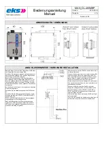
ABMESSUNGEN / DIMENSIONS 


ANSCHLUSSHINWEISE / HARDWARE INSTALLATION 

Rasten Sie das Gerät auf eine Tragschiene DIN EN auf 
und überprüfen Sie den sicheren Halt. 

Verbinden Sie den ankommenden Lichtwellenleiter mit 
dem optischen Empfänger (RX) und den abgehenden 
LWL mit dem optischen Sender (TX). 
Benutzen Sie nur passende LWL-Anschlussstecker 
und verwenden Sie die beigefügten Stopfen um nicht 
benutzte optische Stecker und Kupplungen vor Verun-
reinigungen und Staub zu schützen. Falsche Steckver-
binder können Schäden an den optischen Anschlüssen 
verursachen. 

Knicken Sie die LWL-Kabel nicht zu stark und beachten 
Sie deren Biegeradius. 

Schließen Sie die Datenleitungen am SubD9 Stecker 
an. 

Schließen Sie die Versorgungsspannung gem. Typen-
schild an die Klemmen PWR1 (+) und/oder PWR2 (+) 
sowie GND (-) an. 
PWR1 und PWR2 sind redundante Versorgungsspan-
nungseingänge mit Verpolungsschutz. 

Nach dem Einschalten der Versorgungsspannung 
leuchten alle LEDs (Selbsttest). Wenn die rote FAIL 
LED neben dem optischen Anschluss erlischt, ist die 
optische Verbindung hergestellt.


Snap the system onto the DIN EN rail and check that it 
is securely fastened. 

Connect the incoming fiber to the optical receiver (RX) 
and the outgoing fiber to the optical transmitter (TX). 
Use only suitable optical connectors and apply the at-
tached plugs to unused optical connectors and cou-
plings to prevent them from dust and impurity. 
Using wrong connectors can damage the optical joints. 

Don´t bend the optical fibers too much and refer to the 
specified bending radius. 

Connect the Data wires to the SubD9 connector. 

Supply the voltage specified on the type label to the 
terminals PWR1 (+) and/or PWR2 (+) and GND (-). 
PWR1 and PWR2 are redundant power inputs with 
reverse voltage protection. 

After switching on the power supply, all LEDs will light 
up for a self-test. 
The FAIL LED beneath the optical connection will go off 
to affirm that the optical connection is established. 


Summary of Contents for DL-485MBP/2x

Page 1: ...eite 1 von 8 DL 485MBP DL 485MBP 2x Art Nr 0 1000 64XX ab FW Vers 1 2 Abbildung ähnlich Picture similar eks Engel FOS GmbH Co KG Schützenstraße 2 4 57482 Wenden Hillmicke Germany Tel 49 0 2762 9313 600 Fax 49 0 2762 9313 7906 E Mail info eks engel de Internet www eks engel de ...

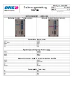
Page 2: ... Former version Aktuelle Version Current version Frontschild Front panel VDC PWR FAIL Fail FAIL Status STA RX RX TX TX Spannungsversorgung Power supply VDC1 PWR1 VDC2 PWR2 Earth Earth GND GND Schraubklemmen SubD9 Screw terminals Sub D9 Earth Earth GND Data GND D D D D 5 VDC 5 VDC Fehlerrelais Fault relay K1 K1 K2 K2 K3 K3 K4 K4 ...

Page 3: ...KONFORMITÄT CE CONFORMITY 4 ENTSORGUNGSHINWEIS DISPOSAL NOTES 4 SYSTEMBESCHREIBUNG SYSTEM DESCRIPTION 5 STATUS LEDS STATUS LEDS 5 FEHLERRELAIS OPTIONAL FAULT RELAY OPTIONAL 5 SUB D 5 SCHRAUBKLEMMEN SCREW TERMINALS 5 ABMESSUNGEN DIMENSIONS 6 ANSCHLUSSHINWEISE HARDWARE INSTALLATION 6 TYPENAUSWAHL UND TECHNISCHE DATEN TYPE SELECTION AND TECHNICAL DATA 7 ZUBEHÖR ACCESSORIES 8 ...

Page 4: ...its may only be operated as described in this manual They may only be used undamaged and according to the specified ambient conditions The devices do not contain any components that must be maintained by the customer Personnel requirements Installation and commissioning of the devices may only be performed by techni cally trained personnel who are familiar with these operating manual All work on e...

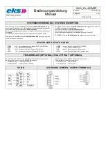
Page 5: ...dant voltage supply Possible failures are displayed by an integrated relay and a fault LED DL 485MBP 2x forward RS 485 Modbus Plus signals to two optical ports STATUS LEDS STATUS LEDS PWR grün Versorgungsspannung liegt an PWR1 oder PWR2 an FAIL rot Sammel Fehlermeldung RX gelb Empfang von Daten auf dieser Schnittstelle STA rot Empfangssignal dieser Schnittstelle fehlerhaft PWR green Power Supply a...

Page 6: ...ante Versorgungsspan nungseingänge mit Verpolungsschutz Nach dem Einschalten der Versorgungsspannung leuchten alle LEDs Selbsttest Wenn die rote FAIL LED neben dem optischen Anschluss erlischt ist die optische Verbindung hergestellt Snap the system onto the DIN EN rail and check that it is securely fastened Connect the incoming fiber to the optical receiver RX and the outgoing fiber to the optical...

Page 7: ... Gerät In compliance with the MODBUS PLUS specification no termination resistors in the device Anschlusslänge Datenkabel Data cable Length 50 m Anschlussstecker Connector 9 polige Sub D Buchse 9 pin female Sub D Status LEDs Control LEDs Stromversorgung grün Datenempfang gelb Status Fehler rot Power supply green Data receive yellow Status Fail red Betriebsspannung Operating voltage 12 30 VDC andere...

Page 8: ... Hutschienenträger Rack 19 For DIN rail carrier Rack 19 10002493 5HE Montage Winkel 5RU mounting brackets Für Universal Hutschienenträger Rack 19 For DIN rail carrier Rack 19 10002494 Wandmontage Kit Wall mount kit Für Längs und Quermontage For horizontal and vertical use 10006625 Dual Mount Kit 10002782 Staubschutzkappe Dust plug ST Simplex 10001448 Staubschutzkappe Dust plug SC Simplex 10001449 ...

Reviews: