Bedienungsanleitung
Manual
MAN_DL-485PBR
Version:
2019-04-05
Freigabe:
U.A.
Seite 5 von 8
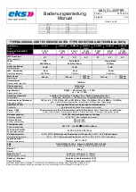
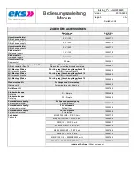
SYSTEMBESCHREIBUNG / SYSTEM DESCRIPTION
Die Geräte des Typs DL-485PBR übertragen
Profibus-DP
oder
Profibus-FMS
Signale über Lichtwellenleiterstrecken.
Sie ersetzen/erweitern entsprechende
Profibus
Zweidraht-Leitungen
.
Per DIP-Schalter kann das System für eine redundante Ringstruktur oder für
Linien- bzw. Punkt-zu-Punkt-Struktur konfiguriert werden.
Zwei Versorgungsspannungseingänge, ermöglichen eine redundante Spannungs-
versorgung.
Ein integriertes Fehlerrelais und eine LED signalisieren auftretende Fehler.
Die Profibus-Datenraten 9,6 - 19,2 - 45,45 - 93,75 - 187,5 - 500 kBit/s,
1,5
– 3 - 6 und 12 MBit/s werden automatisch erkannt.
DL-485PBR systems transmit
Profibus-DP
or
Profibus-FMS
signals via optical
fibers.
They replace/extend equivalent
Profibus Two-Wire
connections
.
The system can be configured for a redundant ring structure or a line respectively
point-to-point structure by DIP switch settings.
Two power inputs allow a redundant voltage supply.
Possible failures are displayed by an integrated relay and a fault LED.
Profibus-data rates with 9,6 - 19,2 - 45,45 - 93,75 - 187,5 - 500 kBit/s,
1,5
– 3 - 6 and 12 MBit/s are detected without configuration.
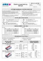
STATUS-LEDS / STATUS-LEDS
PWR
(grün)
: Versorgungsspannung liegt an PWR1 oder PWR2 an
FAIL
(rot) : Sammel-Fehlermeldung
STA
(rot) : Empfangssignal der Kupfer Schnittstelle fehlerhaft
RX
(grün) : Empfang von Daten auf der Kupfer Schnittstelle
Fiberview Status-LEDs:
FAIL
(rot)
: Optisches Empfangssignal fehlerhaft
LMT
(gelb)
: Erreichen der optischen Systemreserve
LNK/ACT
(grün)
: Empfang von Daten auf der LWL Schnittstelle
PWR
(green)
: Power Supply at PWR1 or PWR2
FAIL
(red) : Collective failure signal
STA
(red) : Received signal of the copper interface faulty
RX
(green) : Receiving data on the copper interface
Fiberview Status-LEDs:
FAIL
(red)
: Received optical signal failed
LMT
(yellow)
: Optical budget reserve reached
LNK/ACT
(green)
: Receiving data on the fiber optic interface
BEDIENELEMENTE / CONTROLS
DIP Schalter
DIP
OFF
ON
6
Optischer
Kanal A „Ein“
Optischer
Kanal A „Aus“
5
Optischer
Kanal B „Ein“
Optischer
Kanal B „Aus“
4
Linien- / Pzp-Struktur
Redundanter Ring
3
~
R
W
= 220
Ω
2
~
R
PD
= 390
Ω
1
~
R
PU
= 390
Ω
Auslieferungszustand:
alle Schalter „OFF“
DIP Switch
DIP
OFF
ON
6
Fiber Port A enabled
Fiber Port A disabled
5
Fiber Port B enabled
Fiber Port B disabled
4
Line- / PtP structure
Redundant ring
3
~
R
W
= 220
Ω
2
~
R
PD
= 390
Ω
1
~
R
PU
= 390
Ω
Delivery status:
all DIP “OFF”
FEHLERRELAIS / FAULT RELAY
An den Klemmen K1 bis K3 ist ein potentialfreies Fehlerrelais angeschlossen.
Der aktuelle Zustand wird über die
FAIL LED
signalisiert
Kontakte K1-K2 : Geöffnet im Fehlerfall
Kontakte K2-K3 : Geschlossen im Fehlerfall
Terminals K1 to K3 are linked to a potential free fault relay.
The
FAIL LED
is showing the actual status.
Terminal K1-K2 : normally closed
Terminal K2-K3 : normally open
DIP-SCHALTER /
DIP-SWITCH
SUB-D
SCHRAUBKLEMMEN /
SCREW TERMINALS
Keine Abschlusswiderstände
no termination
Abschlusswiderstände „Ein“
Termination „On“


