Bedienungsanleitung
Manual
MAN_DL-485PBR
Version:
2019-04-05
Freigabe:
U.A.
Seite 6 von 8
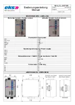
ANSCHLUSSHINWEISE / HARDWARE INSTALLATION
Rasten Sie das Gerät auf eine Tragschiene DIN EN auf
und überprüfen Sie den sicheren Halt.
Verbinden Sie den ankommenden Lichtwellenleiter mit
dem optischen Empfänger (RX) und den abgehenden
LWL mit dem optischen Sender (TX).
Benutzen Sie nur passende LWL-Anschlussstecker
und verwenden Sie die beigefügten Stopfen um nicht
benutzte optische Stecker und Kupplungen vor Verun-
reinigungen und Staub zu schützen. Falsche Steckver-
binder können Schäden an den optischen Anschlüssen
verursachen.
Knicken Sie die LWL-Kabel nicht zu stark und beachten
Sie deren Biegeradius.
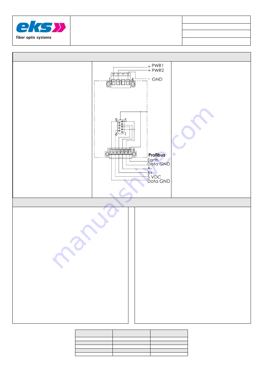
Die Datenleitungen können wahlweise an den Schraub-
klemmen oder am SubD9 Stecker angeschlossen wer-
den.
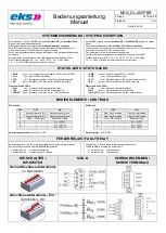
Stellen Sie mit den DIP Schaltern die gewünschte Kon-
figuration ein.
Schließen Sie die Versorgungsspannung gem. Typen-
schild an die Klemmen PWR1 (+) und/oder PWR2 (+)
sowie GND (-) an.
PWR1 und PWR2 sind redundante Versorgungsspan-
nungseingänge mit Verpolungsschutz.
Nach dem Einschalten der Versorgungsspannung
leuchten alle LEDs (Selbsttest). Wenn die rote FAIL
LED neben dem optischen Anschluss erlischt, ist die
optische Verbindung hergestellt.
Snap the system onto the DIN EN rail and check that it
is securely fastened.
Connect the incoming fiber to the optical receiver (RX)
and the outgoing fiber to the optical transmitter (TX).
Use only suitable optical connectors and apply the at-
tached plugs to unused optical connectors and cou-
plings to prevent them from dust and impurity.
Using wrong connectors can damage the optical joints.
Don´t bend the optical fibers too much and refer to the
specified bending radius.
Data wires can be connected to the screw terminal or
to the SubD9 connector alternatively.
Use the DIP switches to set the desired configuration.
Supply the voltage specified on the type label to the
terminals PWR1 (+) and/or PWR2 (+) and GND (-).
PWR1 and PWR2 are redundant power inputs with
reverse voltage protection.
After switching on the power supply, all LEDs will light
up for a self-test.
The FAIL LED beneath the optical connection will go off
to affirm that the optical connection is established.
PROJEKTIERUNG (REDUNDANTER RING) / PROJECT PLANNING (REDUNDANT RING)
Beim Aufbau eines optischen Ringes mit DL-485PBR müssen folgende Punkte
beachtet werden:
DIP 4 muss an und DIP 5 und DIP 6 müssen ausgeschaltet sein
Die min. Antwortzeit aller Slaves (min TSDR) muss auf einen Wert von
11 Bitzeiten (Grundeinstellung) oder mehr eingestellt werden.
Die Slotzeit des Profibus (TSL) muss so eingestellt werden, dass auch
bei Unterbrechung des optischen Ringes die Antworten aller Slaves
innerhalb der Slotzeit am Master eintreffen.
Die minimale Slotzeit hängt ab von:
o
der Datenrate
o
der Gesamtlänge des Lichtwellenleiters
o
der Anzahl der im Ring eingesetzten DL-PBR
Die Slotzeit kann mit der Formel
TSL ≥ max_T
SDR
+ L
LWL
* t
LWL
+ n
DL
* t
DL
berechnet werden, indem die folgenden Werte eingesetzt werden:
o
max_T
SDR
: maximale Antwortzeit der Slaves in Bitzeiten
o
L
LWL
: Länge der gesamten, im Ring eingesetzten LWL in km
Falls von den Ringkopplern Bussegmente ausgehen, die durch
weitere LWL-Koppler oder Repeater über die maximalen elektri-
sche Streckenlängen hinaus verlängert wurden, dann sollten die
Längen der beiden längsten Bussegmente zur Lichtwellenleiter-
länge im Ring hinzu addiert werden
o
t
LWL
: Konstante, die die Bitzeiten pro km Lichtwellenleiter
berücksichtigt(s.Tabelle)
o
n
DL
: Anzahl der im Ring eingesetzten DL-PBR
o
t
DL
: Konstante, die die Laufzeit eines DL-PBR in Bitzeiten
berücksichtigt (s. Tabelle)
When planning a ring structure the following things have to be considered:
Set DIP-switch 4 ON, 5 and 6 to position OFF
The minimum response time of the slaves (min TSDR) must be set to
11 bit times (default) or higher.
The slot time of the Profibus (TSL) must be adjusted to a value high
enough to guarantee that the answers of all slaves arrive at the master
within the slot time even if the optical ring connection is broken.
The minimum slot time depends on:
o
the data rate
o
the length of the optical fibre
o
the number of DL-485PBR in the ring.
It can be calculated with the formula below:
TSL ≥ max_T
SDR
+ L
LWL
* t
LWL
+ n
DL
* t
DL
using the following values:
o
max_T
SDR
: maximum response time of the slaves in bit times
o
L
LWL
: Length of the whole optical fibre in the ring.
The two longest branch lines
– if there are any – should be
added to the length of the fiber in the ring.
o
T
LWL
: Constant considering the bit times per km fiber (see table)
o
n
DL
: Number of DL-485PBR in the ring.
o
t
DL
: Constant considering the delay time (in bit times) of one
DL-485PBR (see table below)
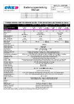
Datenrate [KBit/s]
Data rate [KBit/s]
t
LWL
[Bitzeiten/km]
t
LWL
[Bit times/km]
t
DL
[Bitzeiten]
t
DL
[Bit times]
12.000
240
80
6.000
120
40
3.000
60
20
1.500
30
10
500
10
4


