background image


Bedienungsanleitung 

Manual 

MAN_FIMP-EX 

Version:  3.3.7 

/    18.01.2021 

Freigabe: 

U.A. 

Seite 4 von 8 


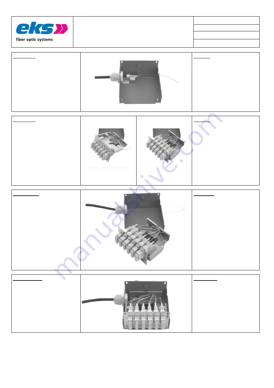
Schritt 7 

 
Möchten Sie zusätzlich die Zugenlastung wie 

rechts im Bild dargestellt einbringen, so 
können Sie diese optional mit der 
Artikelnummer 0 220 790 bestellen. 


Step 7 

 
If you like to use an extra strain relief as 

shown in the picture on the left, you can 
order it separetly (art.no. 0 220 790). 


Schritt 8 

 
Sie können die Spleißkassette in zwei 

verschiedenen Varianten in das Gehäuse 
einbauen: 


1.) 

Obenliegende Spleißkassette, 
damit befinden sich die ge-
steckten Pigtails auf der Unter-
seite (Bild links). 

Weiter mit 

Punkt 9A. 

 
2.) 

Sowohl der Spleißkassette als 
auch die gesteckten Pigtails 
befinden sich auf der Oberseite 
(Bild rechts). 

Weiter mit Punkt 

9B.


Spleißhalter oben   /   Pigtails unten   Top: 

Splice Tray   /   Bottom: Pigtails  


Spleißhalter und Pigtails oben 

Pigtails and Splice Tray on top side 

Step 8 

 
 You can assemble the splice cassette into 

the case in two different ways: 


1.) splice cassette up: the pigtails are 

situated on the bottom (left 
picture) 

Proceed with Step 9A.


2.) Both the splice cassette and the 

pigtails are situated at the top 
(right picture). 

Proceed with 

Step 9B.


Schritt 9A 

 
Spleißen Sie nun die Faserenden und legen 

Sie die überschüssigen Längen in der 
Spleißablage (Gehäuse-Innenraum) ab. 
Schrauben Sie die Spleißablage mit der 
Kreuzschraube wieder fest. 

 
Sorgen Sie mittels der beigefügten Kabel-

binder für eine ausreichende Zugent-
lastung. 


Step 9A 

 
Splice the fiber optics and put them into the 

splice tray. Be careful when putting the 
overlength of the fiber optic cable into 
the housing. 

 
To ensure a sufficient strain relief, fasten the 

fiber optics with the cable ties included 
in the packaging. 


Schritt 10A 

 
Montieren Sie die Spleißkassette mit zwei 

Inbusschrauben in der unteren Gehäuse-
halbschale. 


Step 10A 

 
Assemble the splice cassette into the half 

shell of the housing by using two 
screws. 


Summary of Contents for FIMP-EX

Page 1: ...thaften Personen oder Anlageschäden führen kann Bitte lesen Sie die Anleitung vor Inbetriebnahme der FIMP EX Geräte aufmerksam durch Ordnungsgemäßer Transport korrekte Lagerung und Installation sowie sorgfältige Bedienung und Instandhaltung der FIMP EX sind entscheidend für den sicheren Betrieb This manual contains important notes and warnings Their ignoration can cause serious injuries or damages...

Page 2: ...d cable gland It is available with the following couplings SMA ST SC LC and E 2000 Please ask for other types of couplings Addittionally FIMP EX can be mounted with different kind of couplings The case is made of stainless steel powder coated and contains a clip for DIN Rail mounting Optionally a wall mount kit and a 19 rack mount kit are available FIMP EX can be used with all kind of fibers such ...

Page 3: ...ch die andere vorgestanzte Öffnung im Gehäuse aus Befestigen Sie die Kabelverschraubung M20 die optional erhältlich ist Step 4 To fit in the cable gland please remove the perforated metal ear as shown in the picture on the left Should you need two cable entries please remove the other perforated hole opposite the normal cable entry Fasten the M20 cable gland which you can buy seperately Schritt 5 ...

Page 4: ...ils and Splice Tray on top side Step 8 You can assemble the splice cassette into the case in two different ways 1 splice cassette up the pigtails are situated on the bottom left picture Proceed with Step 9A 2 Both the splice cassette and the pigtails are situated at the top right picture Proceed with Step 9B Schritt 9A Spleißen Sie nun die Faserenden und legen Sie die überschüssigen Längen in der ...

Page 5: ...um ab Schrauben Sie die Spleißablage mit der Kreuzschraube wieder fest Step 9B Splice the fiber optics and put them into the splice tray Be careful when putting the overlength of the fiber optic cable into the housing Schritt 10B Montieren Sie den Spleißeinsatz mit zwei Inbusschrauben in der unteren Gehäuse halbschale Step 10B Assemble the splice cassette into the half shell of the housing by usin...

Page 6: ...onto the rail DIN EN at the bottom side see left picture press it against the spring force to the top 1 and then towards the mounting plate 2 The system latches as shown in the picture at the left Check the correct holding Attention Please only use the correct optical connectors for the fiber optic system Using incorrect connectors can cause damage to the fiber optic system Note that connectors wi...

Page 7: ...Bedienungsanleitung Manual MAN_FIMP EX Version 3 3 7 18 01 2021 Freigabe U A Seite 7 von 8 Technische Daten Technical Data ...

Page 8: ...onnector ST SC Ausführung 9 125µm Type 9 125µm 6xST Duplex SM 6xSC Duplex SM Bestell Nr FIMP EX Order No 0600136196 04 0600136396 04 Faser Fiber Single Mode 9 125µm LWL Anschluss Fiber connector ST SC 0 PC Kabelzuführung Cable Entry 1 x Verschraubung M20 1 x Cable Gland M20 Gewicht Weight 450 g Maße B x H x T Dimensions W x H x D B 61 mm H 100 mm T 115 mm W 61 mm H 100 mm D 115 mm Gehäuse Case Ede...

Reviews: