background image


Bedienungsanleitung 

Manual 

MAN_FIMP_S 

Version:  6.1.8 

/ 10.07.2018 

Freigabe: 

U.A. 

Seite 5 von 7 


Schritt 8 


Verschrauben

 Sie das Gehäuse. Zur 

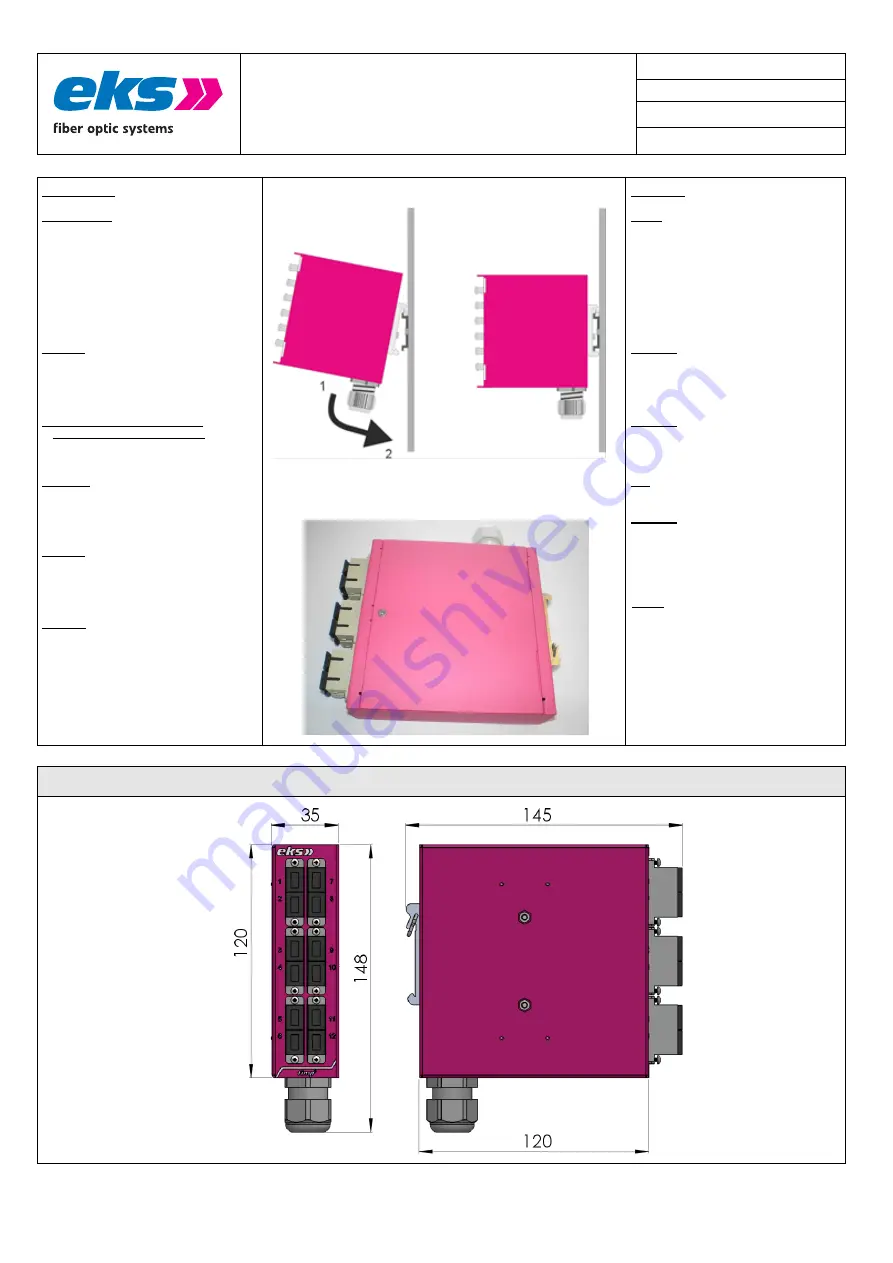
Montage (siehe Bild rechts) rasten Sie bitte 
den FIMP an der Oberseite in die 
Tragschiene DIN ein und drücken es dann 
gegen die Federkraft nach unten (1) und 
anschließend zur Montageplatte hin (2). 
Das System FIMP verriegelt wie im Bild 
rechts dargestellt. Zur Demontage befolgen 
Sie die oben genannten Schritte in 
umgekehrter Reihenfolge. Überprüfen Sie 
den festen Halt des FIMP.


Achtung: 

Benutzen Sie nur die zugehörigen 

LWL-Anschlussstecker. Wir weisen 
ausdrücklich daraufhin, dass der Anschluss 
mit falschen Steckverbindern Schäden an 
den optischen Anschlüssen hervorrufen 
kann! 

Achtung: Sehen Sie nicht in das 

Faserende oder die Kupplung!

 Das ge-

bündelte und abhängig von der 
Wellenlänge sichtbare oder unsichtbare 
Licht kann zu Augenschäden führen! 

Benutzen

 Sie die beigefügten Stopfen, um 

Sender und Empfänger des LWL-Systems 
im nicht eingebauten oder nicht benutzten 
Zustand vor Verunreinigungen oder Staub 
zu schützen. 

Achtung: 

Knicken Sie das LWL-Kabel nicht 

zu stark und beachten Sie den Biegeradius 
des Kabels. Andernfalls kann das Kabel 
beschädigt werden und /oder die 
Kommunikation zwischen den LWL-
Wandlern nicht mehr gewährleistet werden. 

Hinweis:


Wenn Sie 

FIMP als Patchfeld


benutzen wollen, z.B. bei bereits fertig 
konfektionierten LWL-Kabeln, dann stecken 
sie die Stecker in der von Ihnen 
gewünschten Reihenfolge in die Kupplung. 
Achten Sie darauf, die Fasern ohne zu 
knicken in das Gehäuse zu legen, wie in 
Schritt 6 beschrieben. Weiter mit Schritt 7. 


Step 8 


Screw

 the two parts of the case together 

and tighten the screws carefully. For 
mounting the FIMP please engage it 
onto the DIN rail at the bottom side (see 
left picture), press it against the spring 
force to the top (1) and then towards the 
mounting plate (2). The system latches 
as shown in the picture at the right. 
Check the correct holding. Please refer 
to the above mentioned steps in reverse 
order to demount the FIMP. 

Attention: 

Please only use the correct 

optical connectors for the fiber optic 
system. Using incorrect connectors can 
cause damage to the fiber optic system. 
Note that connectors with a latch can only 
be mounted in a defined position. 

Attention: 

Do not stare into the optical fiber 

or the coupling. Visible and non-visible 
light (depending on its wavelength) of the 
optical transmitter can cause damage to 
the eyes! 

Use

 the plug to protect the unused optical 

receiver and transmitter against dirt and 
dust. 

Attention: 

Don't bend the fiber optic cable! 

Please  to the 

manufacturer’s cable 

specifications. Otherwise the fiber optic 
cable might be damaged and the 
converters’ communication can no longer 
be warranted. 


NOTE:

 When you want to use 

FIMP as a 

patch field

, e.g. with pre-assembled fiber 

optic cables, please connect the fiber to 
the coupling after having chosen your 
specific order. Be careful not to bend the 
fiber when putting it into the case as 
described in Step 6. Then proceed with 
Step 7. 


Abmessungen / Dimensions 


Summary of Contents for FIMP S

Page 1: ... ernsthaften Personen oder Anlageschäden führen kann Bitte lesen Sie die Anleitung vor Inbetriebnahme des FIMP Gerätes aufmerksam durch Ord nungsgemäßer Transport korrekte Lagerung und Installation sowie sorgfältige Bedienung und Instandhaltung de FIMP sind entscheidend für den sicheren Betrieb This manual contains important notes and warnings Their ignoration can cause serious injuries or damages...

Page 2: ...g couplings ST SC LC and E 2000 Please ask for other types of coupling Additionally FIMP can be mounted with different kind of couplings If only one splice holder is used it is possible to turn it 4x90 Thus different positions are possible There is also a fixture that keeps the splice holder in its position Apart from that there are shorter blank holders that allow an easier application of the pig...

Page 3: ...g so können Sie diese optional mit der Artikelnummer 10600000 13 bestellen Step 4 To fit in the cable gland please remove the perforated metal ear as shown in the picture on the left Should you need two cable entries please remove the other perforated hole opposite the normal cable entry Fasten the M20 cable gland which you can buy seperately Then fasten the cable gland in the case If you also wan...

Page 4: ...nge kann verwendet werden Spleißkamm für Schrumpfspleißschutz kann optional mit der Artikelnummer 1060000019 bestellt werden Dieser ist geeignet für 6 Schrumpfspleißschutze mit 3 mm oder 12 Schrumpfspleißschutze mit 2 mm Durchmesser Die Länge von 45 mm sollte nicht überschritten werden The splice holder can be mounted in 2 different positions see left picture Furthermore it is possible to have two...

Page 5: ...in der von Ihnen gewünschten Reihenfolge in die Kupplung Achten Sie darauf die Fasern ohne zu knicken in das Gehäuse zu legen wie in Schritt 6 beschrieben Weiter mit Schritt 7 Step 8 Screw the two parts of the case together and tighten the screws carefully For mounting the FIMP please engage it onto the DIN rail at the bottom side see left picture press it against the spring force to the top 1 and...

Page 6: ...300 62493 00 06300 62596 00 Faser Fiber Multi Mode 50 125µm OM3 LWL Anschluss Fiber connector ST SC LC E 2000 Ausführung 9 125µm Type 9 125µm 6xST Duplex SM 6xSC Duplex SM 6xSC 8 APC Duplex SM 3xLC Quattro SM 6xE2000 Duplex SM 6xE200 8 APC Duplex SM Bestell Nr FIMP S Order No 06300 36196 00 06300 36396 00 06300 38396 00 06300 36493 00 06300 36596 00 06300 38596 00 Faser Fiber Single Mode 9 125µm L...

Page 7: ...ugentlastung Strain relief 1060000013 Blindplatte Blind plug SC Duplex 1060000020 Blindplatte Blind plug Smarthole 0600 E 90005 Blindplatte Blind plug SC RJ 1060000021 Spleißkamm Splice holder 1060000022 Spleißschutz Splice protection 1060000023 Kabelbinder Cable tie 1060000008 Klemmplatte Hutschiene DIN Clamping plate DIN rail 0600 E 90012 Dual Mount Kit Dual Mount Kit 1000000200 22 Technische Än...

Reviews: