4
www.eksmaoptics.com
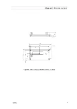
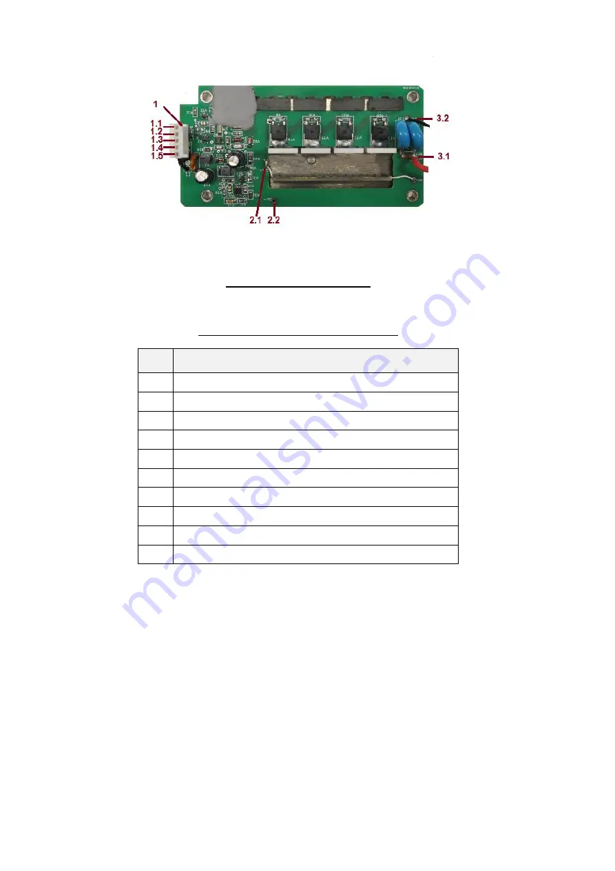
Figure 2.
Top view of the driver
Table 3.
Ports seen in top view of the driver
#
Port
1
Connector for DC power suppling and HV driving
1.1
Pin1
SYNC IN input
1.2
Pin2
GND
1.3
Pin3
+DC power input
1.4
Pin4
N.C.
1.5
Pin5
GND
2.1
HV pulse output pin +OUT
2.2
GND output pin
3.1
+HV Power input pin
3.2
GND input pin from HV supply


