HIGH VOLTAGE POWER SUPPLY HVS-100
3
Visit
for new products and prices
•
Rev. 20220211
1
2
3
4
7
5
6
8
9
10
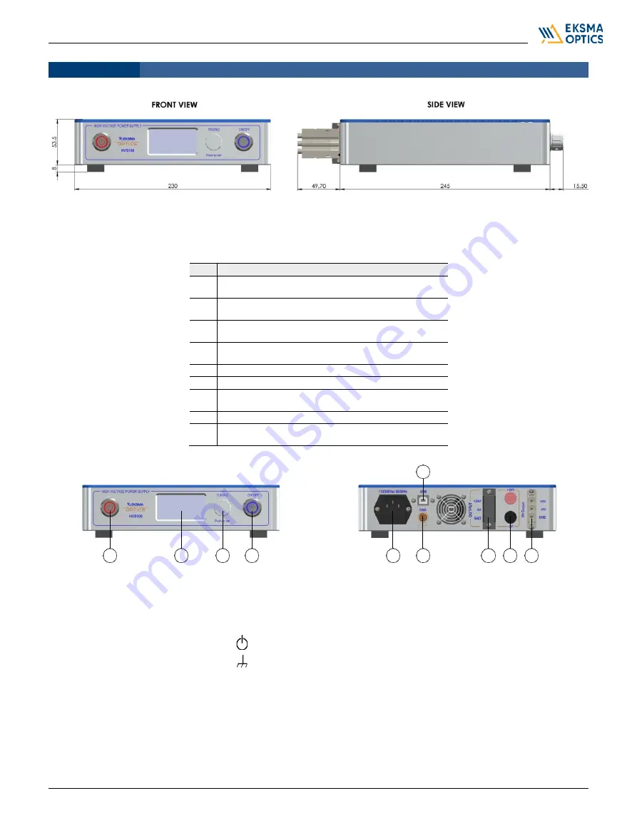
DEVICE LAYOUT
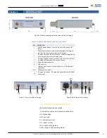
Figure 1. Outline drawing and dimensions of the HV supply
Table 1.
CONTROLS AND CONNECTIONS OF THE HV SUPPLY
NO. DESCRIPTION
1
ON/OFF power button: It has priority over all operations for
safety.
2
OLED screen interface: Used to display voltage of HV output.
Indicates the current consumed from HV output.
3
HV output tuning encoder with button: Used for voltage tuning
of HV output. Press to set the tuned value.
4
HV output ON/OFF button with LED: Used to turn ON/OFF the
HV output. LED indicates if HV output is active.
5
AC power input connector.
6
GND terminal.
7
USB connector. Used to control the device via “CAN Browser”
application.
8, 9
24V output connectors.
10
HV output connector. -HV output is only available for HVS100-
2x60 model.
Figure 2. Front view of the HV supply
Figure 3. Back view of the HV supply
1.1.
SYMBOLS AND ABBREVIATIONS
Symbol for device power switch
Symbol for chassis earth, potential safety earth.
HV
–
high voltage.
GND
–
ground.
AC
–
alternating current.
DC
–
direct current.
LED
–
light-emitting diode.
OLED
–
organic light-emitting diode.
Chapter 1


