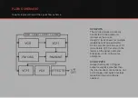
FLOW SCHEMATIC
Graphic representtion of the signal flow scheme
CV INPUTS
The CV input jacks are directly
connected to the parameter
marked on the panel.
Using CV jacks allows for multiple
modulations of one parameter.
As an example you can use LFO1
to modulate VCF Cut off with the
faders on the panel, and send
EG signal via CV to the same
parameter.
CV OUTPUTS
Notice that the EG CV Signal
output is slighlty smoother then
the internal direct connections. For
extra snappy and quick envelope
modultion internal routing is
adviced.
Summary of Contents for ES101
Page 1: ...USER GUIDE ...


