ELAD QSF-06
User Manual Rev 1.0 04/2016
© 2016 ELAD S.r.l. All rights reserved. No part of this document may be reproduced, published, used, disclosed or disseminated in any form or
by any means, electronic, photocopying or otherwise, without prior written permission of ELAD S.r.l.
6
3
Hardware Description
3.1
Front Panel Description
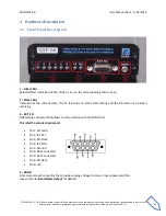
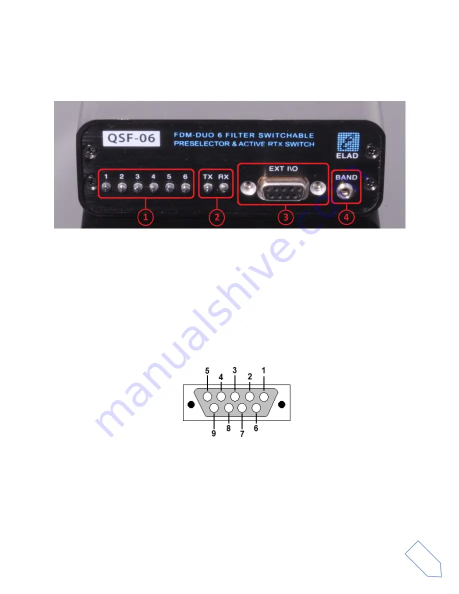
1 – Filter LEDs
Selected filter indication. When a filter is in use, the corresponding LED turns on.
2 – State LEDs
Indication of the current state. The TX led turns on when transmitting and the RX led turns on when
receiving .
3 – EXT I/O
DB9 female connector that allows communication with the FDM-DUO.
This is NOT a standard serial port.
Pin 1: SPI Latch
Pin 2: I2C SCL
Pin 3: SPI Clock
Pin 4: I2C SDA
Pin 5: Ground
Pin 6: Not Connected
Pin 7: Not Connected
Pin 8: SPI Data
Pin 9: +5V
4 – BAND
3.5mm stereo jack connector that provides analog voltage to drive a linear power amplifier
(see section
for details).


