EM78P911A
8-bit Micro-controller
__________________________________________________________________________________________________________________________________________________________________
* This specification is subject to change without notice.
~ ~
24
12/19/2005 (V2.1)
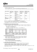
VII.9.3
Ring detect circuit
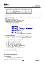
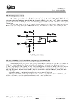
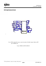
When Vdd is applied to the circuit, the RC network will charge cap C1 to Vdd holding /RING TIME off . The
resistor network R2 to R3 attenuates the incoming power ring applied to the top of R2. The values given have been chosen to
provide a sufficient voltage at DET1 pin, to turn on the Schmitt trigger input. When Vt+ of the Schmitt is exceeded, cap C1
will discharge.
The value of R1 and C1 must be chosen to hold the /RING TIME pin voltage below the Vt+ of the Schmitt between
the individual cycle of the power ring. With /RINGTIME enabled, this signal will be a /RD signal in RA throught a buffer.
Fig.14 ring detect circuit
VII.10 DTMF ( Dual Tone Multi Frequency ) Tone Generator
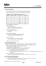
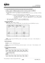
Built-in DTMF generator can generate dialing tone signals for telephone of dialing tone type. There are two kinds of
DTMF tone . One is the group of row frequency, the other is the group of column frequency, each group has 4 kinds of
frequency , user can get 16 kinds of DTMF frequency totally. DTMF generator contains a row frequency sine wave generator
for generating the DTMF signal which selected by low order 4 bits of RB and a column frequency sine wave generator for
generating the DTMF signal which selected by high order 4 bits of RB. This block can generate single tone by filling one bit
zero to this register.
If all the values are high , the power of DTMF will turn off until one or two low values.
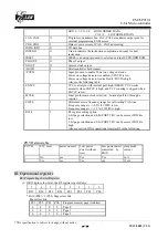
Either high or low 4 bits must be set by an effective value, otherwise, if any ineffective value or both 4 bits are load
effective value, tone output will be disable. Recommend value refer to table as follow please :
Vdd
/Ring Time
Det1
/RD
C1
R3
R1
R2
/Ring Time


