EM78P911A
8-bit Micro-controller
__________________________________________________________________________________________________________________________________________________________________
* This specification is subject to change without notice.
~ ~
29
12/19/2005 (V2.1)
VII.12 CALL WAITING Function Description
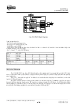
Fig.19 Call Waiting Block Diagram
Call Waiting service works by alerting a customer engaged in a telephone call to a new incoming call. This way the
customer can still receive important calls while engaged in a current call. The CALL WAITING DECODER can detect
CAS(Call-Waiting Alerting Signal 2130Hz plus 2750Hz) and generate a valid signal on the data pins.
The call waiting decoder is designed to support the Caller Number Deliver feature, which is offered by regional Bell
Operating Companies. The call waiting decoder has four blocks, including pre-amplifier, band pass filter, level detect and
digital detection algorithm.
In a typical application, after enabling CW circuit (by RE BIT7 CWPWR) this IC receives Tip and Ring signals
from twisted pairs. The signals as inputs of pre-amplifier, and the amplifier sends input signal to a band pass filter. Once
the signal is filtered, the digital detection block decodes the information and sends it to R3 register bit7 . The output data
made available at R3 CAS bit.
The data is CAS signals. The CAS is normal high. When this IC detects 2130Hz and 2750Hz frequency, then CAS
pin goes to low.
CWTIP
Filter
Digital
Detection
Algorithm
Vdd/2
Band
Pass
Detect
Level
Voltage
Reference
Clock
Generator
GAIN
CAS
0: DATA valid
1: DATA invalid
call waiting circuit power control
FSK BLOCK
snd
SDT Block
TIP
RING
-
+
FSK data
/SDT


