eSE Series
6
•
Pad Diagrams (V1.1) 01.17.2005
(These diagrams are subject to change without further notice)
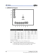
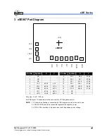
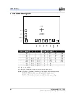
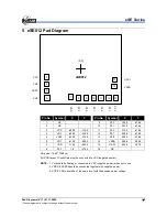
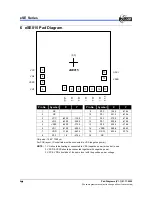
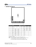
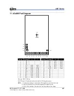
6 eSE015 Pad Diagram
VO2
VSSC
VO1
(0,0)
eSE015
3
4
5
6
7
8
9
10
11
12
13
P2.0
P2.
1
P2.
2
P3.
1
P3.
2
P3.
3
VDD
VCC
14
15
VSSD
OSCI
Pin No.
Symbol
X
Y
Pin No.
Symbol
X
Y
1 NC
9 P3.2
126.5
-478.4
2 NC
10 P3.1
251.2
-478.4
3 VCC
-630.0
-130.9 11 P2.2
375.9
-478.4
4 VO2
-630.0
-250.9 12 P2.1
500.6
-478.4
5 VSSC
-630.0
-370.9 13 P2.0
625.3
-478.4
6 VO1
-610.0
-490.9 14
VSSD
588.4
-286.2
7 VDD
-118.2
-463.4 15 OSCI
603.4
-137.2
8 P3.3 1.8
-478.4 16 NC
Chip size
:
1540 * 1290
µ
m
For PCB layout, IC substrate must be connected to VSS (negative power).
NOTE:
1. VO should be floating or connected to VSS (negative power) when not in use.
2. VSSD & VSSC should be connected together with negative power.
3. VCC & VDD should be of the same level with the positive power voltage.


