1( LW2110, LW2110PK2B)
0
0
R
T
-
F
R
D
Wireless Digital Transceiver
ELANsat
Page of 7
2007.12.06
www.elansat.com
Version: 1.0
5
PCB layout guideline
Any metal (including PCB track and holding screw) around the antenna will result in changing
impedance and radiation pattern of the antenna. These two parameters are the most important for
antenna performance. Reserve space around the antenna as much as possible.
Connect all parts as close as possible to the pins of module and reduce the length of routing
traces, to help on good audio performance, proper antenna pattern and EMC.
When designing the receiver module in wireless speakers and headphones, the important design
considerations are as follows:
1.
Keep metal objects away from the antenna by 3 cm distance at least to avoid degradation on
the antenna. For example, speaker unit, transformer, adaptor, wire, cable and other big metal
object beside antenna will degrade the antenna performance.
2.
Use regulated DC-power-supply to the modules, and separate the DC-power-supply of module
with the other circuits.
Antenna
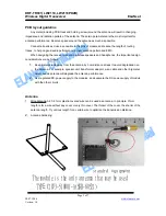
1. Wire Antenna: A 27~31mm plastic-covered wire can be used as antenna. In principle, 31mm
length is for a wire without any cover or very thin cover. The thicker of the cover, the shorter of the
antenna length. Try various length for a certain wire to optimize the transmission distance.
2.
Antenna Soldering:
standrd equipment
The module is the only antenna that may be used
TYPE:C1073-510001-A(SSR-80521)

