background image

17

GAS TAPS

Periodic lubrication of the gas taps must be 

carried out by specialist personnel only.

In the event of operating faults in the gas 

taps, call the Service Department.

INSIDE OF OVEN

The oven should always be cleaned after 

use when it has cooled down.

The cavity should be cleaned using a mild 

detergent solution and warm water.

Suitable proprietary chemical cleaners 

may be used after first consulting with the 


manufacturers recommendations and te-

sting a small sample of the oven cavity. 

Abrasive cleaning agents or scouring pads/

cloths should not be used on the cavity sur-

face.

NOTE:

 The manufacturers of this applian-

ce will accept no responsibility for damage 

caused by chemical or abrasive cleaning.

Let the oven cool down and pay special 

attention  no  to  touch  the  hot  heating 

elements inside the oven cavity.

Fire risk! Do not store flammable material 

in the oven.

OVEN DOOR

The internal glass of the oven door can be 

easily removed for cleaning by unscrewing 

the two lateral fixing screws (fig. 6.1).

BURNERS

They can be removed and washed with 

soapy water only.

They will remain always perfect if cleaned 

with products used for silverware.

After cleaning or wash, check that burner- 

caps and burner-heads are dry before pla-

cing them in the respective housings.
Check that the electrode 

S

 (figs. 6.2, 6.4) 

next to each burner is always clean to en-

sure trouble-free sparking.

Note:  The  electrode  “S”  must  be  very 

carefully cleaned.

To avoid damage to the electric ignition 

do not use it when the burners are not 

in place.

CORRECT REPLACEMENT OF THE

SEMI-RAPID AND RAPID BURNERS

It is very important to check that the burner 

flame  distributor  “

F

” and the cap “

C

” has 

been  correctly  positioned  (see  figs.  6.2- 

6.3) - failure to do so can cause serious 

problems.

CORRECT REPLACEMENT OF THE 

TRIPLE RING BURNER

The triple ring burner must be correctly po-

sitioned (see fig. 6.6); the burner rib must 

be enter in their logement as shown by the 

arrow (see fig. 6.4).

The burner correctly positioned must not 

rotate (fig. 6.5).

Then position the cap 

A

 and the ring 

B


(figs. 6.5 - 6.6).

Fig. 6.1

Summary of Contents for EEC 863

Page 1: ...Made in Italy H O M E A P P L I A N C E S 100 ELBAQUALITY MADE IN ITALY Instructions for the use Installation advices DUAL FUEL COOKERS Models EEC 863 EEC 963 ...

Page 2: ...lease preserve this booklet carefully It may be useful in futu re either to yourself or to others in the event that doubts should arise relating to its operation This appliance must be used only for the task it has expli citly been designed for that is for cooking foodstuffs Any other form of usage is to be considered as inappropriate and therefore dangerous The manufacturer declines all responsib...

Page 3: ...environment Read the instructions carefully before installing and using the ap pliance CAUTION this apparatus must only be installed in a permanently ventilated room in compliance with the applicable regulations FIRST USE OF THE OVEN It is advised to follow these instructions Furnish the interior of the oven as described at chapter Clea ning and maintenance Switch on the empty oven on max to elimi...

Page 4: ... another model before disposing of it it is recommended that it be made inoperative in an appropriate manner in accordance to health and environmental protection regulations ensuring in particular that all potentially hazardous parts be made harmless especially in relation to children who could play with unused appliances After use ensure that the knobs are in the off position Household appliances...

Page 5: ...ap pliance The various components of the appliance are recyclable Dispo se of them in accordance with the regulations in force in your country If the appliance is to be scrapped remove the power cord Always use oven gloves when removing the shelf and food tray from the oven whilst hot Do not hang towels dishcloths or other items on the cooker or its handle as this could be a fire hazard Clean the ...

Page 6: ... AND ELECTRICAL PLATES 1 Semi rapid burner SR 1 75 kW 2 Rapid burner R 3 00 kW 3 Triple ring burner TR 3 50 kW 4 Electrical plate Ø 180 mm Normal 1500 W Fig 1 1 Fig 1 2 COOKING HOB 1 2 3 1 4 Models EEC 963 Models EEC 863 ...

Page 7: ... knob 3 Front left burner control knob 4 Central right burner control knob 5 Rear central electrical plate control knob 6 60 minutes alarm control knob 7 Gas burners electronic igniter pushbutton 8 Oven light rotisserie control button 9 Electric oven grill indicator light 10 Electrical plate indicator light Fig 2 2 Models EEC 963 Models EEC 863 ...

Page 8: ...reduced rate The maximum aperture position per mits rapid boiling of liquids whereas the minimum aperture position allows slower warming of food or maintaining boiling conditions of liquids To reduce the gas flow to minimum rotate the knob further anti clockwise to point the indicator towards the small flame symbol Other intermediate operating adjustments can be achieved by posi tioning the indica...

Page 9: ...o des situated next to the burner will light the selected burner In the case of a mains failure light the burner with a match or lighted taper 3 Adjust the gas valve to the desired po sition To turn it off turn the knob towards the right up to the safety click If your local gas supply makes it difficult to light the burner with the knob set to maxi mum set the knob to minimum and repeat the operat...

Page 10: ... pan support When using a WOK you need to place the supplied stand in the burner to avoid any faulty operation of the triple ring burner Figs 3 5a 3 5b IMPORTANT The special grille for wok pans fig 3 5b MUST BE PLACED ONLY over the pan rest for the triple ring burner WRONG CORRECT Fig 3 5a Fig 3 5b ...

Page 11: ...il turn the heat down to the level desired Remember that the hotplate will continue to produce heat for about five minutes after it has been turned off While using the electric hotplate you must avoid keeping it on without something on it avoid pouring liquids on it while it is hot use flat bottomed electric hotplate type pots and pans only use cooking receptacles which cover as much of the surfac...

Page 12: ... boiling i e boiled meats spaghetti soups continuations of steam cooking of roasts stews potatoes For every kind of frying cutlets uncovered cooking i e risotto Browning of meats roasted potatoes fried fish omelet tes and for boiling large quantities of water Fast frying grilled steaks etc 0 Position of switch 1 2 3 2 3 4 4 4 5 6 ELECTRIC HOTPLATE USAGE TABLE After a short period of use experience...

Page 13: ...wer The numbers correspond to the temperature shown in the table 4 2 The elements will turn on and off automatically depending on the tem perature required commanded by the thermostat Position grill element in opera tion without temperature control see specific paragraph The automatic turning on and off of the elements is signalled by a light above the knob GENERAL FEATURES The oven is furnished c...

Page 14: ...ote It is recommended that you do not grill for longer than 30 minutes at any one time The oven door becomes very hot during operation Keep children away OVEN COOKING To cook before introducing the food prehe at the oven to the desired temperature When the oven has reached the desired temperature introduce the food control the cooking time and tum off the oven 5 minutes before the theoretical time...

Page 15: ...e cooked onto the rod being careful to secure it in the center with the special forks Insert the rod into the motor opening and rest it onto the support of the spit collar then remove the grip by turning it to the left The rotation direction of the rotisserie can be either clockwise or counter clockwise Fig 4 4 OVEN LIGHT The oven is equipped with a light that illu minates the oven to enable visua...

Page 16: ... to be touched and may contain sharp or rough edges that may cause injury ENAMELLED PARTS All the enamelled parts must be cleaned with a sponge and soapy water or other non abrasive products Dry preferably with a microfibre or soft cloth Acidic substances like lemon juice tomato sauce vinegar etc can damage the ena mel if left too long STAINLESS STEEL ALUMINIUM PARTS PAINTED AND SILK SCRE EN PRINT...

Page 17: ...e easily removed for cleaning by unscrewing the two lateral fixing screws fig 6 1 BURNERS They can be removed and washed with soapy water only They will remain always perfect if cleaned with products used for silverware After cleaning or wash check that burner caps and burner heads are dry before pla cing them in the respective housings Check that the electrode S figs 6 2 6 4 next to each burner i...

Page 18: ...18 A B S Fig 6 4 Fig 6 5 Fig 6 6 S F C Fig 6 3 Fig 6 2 ...

Page 19: ...lamp to avoid the possibility of electric shock Let the oven cavity and the heating elements to cool down Switch off the electrical supply Remove the protective cover Unscrew and replace the bulb with a new one suitable for high temperatu res 300 C having the following speci fications 230V E14 and same power check watt power as stamped in the bulb itself of the replaced bulb Refit the protective c...

Page 20: ...nty The appliance must be installed in compliance with regulations in force in your country and in observation of the manufacturer s instructions Always disconnect the appliance from the power supply before carrying out any main tenance operations or repairs Some appliances are supplied with a protective film on steel and aluminium parts This film must be removed before using the cooker Advice for...

Page 21: ...etween the side of the cooker and the furniture The veneered syntetical material and the glue used must be resistant to a temperature of 90 C in order to avoid ungluing or deformations Curtains must not be fitted immediatly behind appliance or within 500 mm of the sides If the cooker is located on a pedestal it is necessary to provide safety measures to prevent falling out The appliance must be ho...

Page 22: ...ns The openings should be near the floor and preferably on the side opposite the exhaust for combustion products and must be so made that they cannot be blocked from either the outside or the outside When these openings cannot be made the necessary air can come from an adjacent room which is ventilated as required as long as it is not a bed room or a danger area in com pliance with applicable loca...

Page 23: ...ation label attached on the appliance Appliances supplied for use on Natural gas they are adjusted for this gas only and cannot be used on any other gas LPG or Town gas without modification The appliances are manufactured for conversion to LPG and Town gas Appliances supplied for use on LPG they are adjusted for this gas only and cannot be used on any other gas Natural or Town gas without modifica...

Page 24: ...making sure that you place the sealing washer between them as shown in Fig 8 2 ok ok THE PIPE DOES NOT CROSS THE REAR PANEL OF THE COOKER IN CASE OF CROSSING THE BACK PANEL ENSURE THE PIPE IS POSITIONED CLOSE TO THE BOTTOM PART OF THE APPLIANCE IF CONNECTING THE APPLIANCE TO A GAS CYLINDER POSITIONED INSIDE THE GAS COMPARTMENT FOLLOW ALSO THE INFORMATION AS PER CHAPTER GAS CYLINDER CONNECTION AND ...

Page 25: ...longer than 750 mm or refer to applicable local regulations and does not come into contact with sharp edges corners or moving parts Use a single rubber hose only never connect the appliance with more than one rubber hose the hose is not under tension twisted kinked or too tightly bent neither while the appliance is in use nor while it is being connected or disconnected the hose does not come into ...

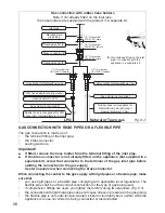
Page 26: ... PIPES OR A FLEXIBLE PIPE The gas connection is made up of the terminal fitting of the inlet pipe the brass connector sealing washers Important If fitted remove the hose holder from the terminal fitting of the inlet pipe If the brass connector is not already fitted on the appliance but supplied in a separate kit screw that connector to the terminal of the gas inlet pipe before starting the connect...

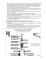
Page 27: ... the appliance should be closed when the cooker is not in use you inform the customer that the rigid or flexible pipe should not be subjected to corro sion by acidic cleaning agents After connecting the cooker to the gas supply make sure that you check that the connections are correctly sealed using a soapy solution but never a naked flame check whether the injectors are correct for the type of ga...

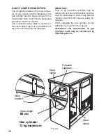
Page 28: ... over the hose connectors to the full depth IMPORTANT Only 13 kg maximum cylinders may be used in the cylinder compartment and they must be positioned in such a way that the regulator and shut off cock are easily ac cessible When changing the gas cylinder do not withdraw the hose from the support Installation and replacement of gas cylinders must only be carried out by qualified persons Gas cylind...

Page 29: ...f this obligation TABLE FOR THE CHOICE OF THE INJECTORS BURNERS Nominal power kW Reduced power kW LPG G30 28 30 mbar G31 37 mbar Natural Gas G20 20 mbar Town Gas G110 8 mbar Ø injector 1 100 mm Ø injector 1 100 mm Ø injector 1 100 mm Semi rapid SR 1 75 0 45 66 101 192 Rapid R 3 00 0 75 87 129 280 Triple ring TR 3 50 1 50 93 135 310 AIR VENT NECESSARY FOR GAS COMBUSTION 2 m3 h x kW BURNERS Air nece...

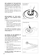
Page 30: ...cooktop Using a wrench substitute the nozzle injectors J figs 8 5a 8 5b with tho se most suitable for the kind of gas for which it is to be used The burners are conceived in such a way so as not to require the regulation of the primary air ADJUSTING OF THE MINIMUM OF THE COOKTOP BURNERS In the minimum position the flame must have a length of about 4 mm and must re main lit even with a quick turn f...

Page 31: ...t be carri ed out by qualified personnel in accor dance with current regulations The appliance must be connected to the mains checking that the voltage corresponds to the value given in the rating plate and that the electrical ca ble sections can withstand the load specified on the plate Only for models without electric hotpla te EEC 863 The cooker is supplied without a power supply plug and there...

Page 32: ...e for the current requirements of the appliance see the section Feeder cable specifications Connect the wires to the terminal block B as shown in the diagram in figure 9 2 Take up any slack in the cable and secure with the cable clamp C Replace the cover A Note The earth conductor must be left about 3 cm longer than the others FEEDER CABLE SPECIFICATIONS TYPE H05RR F Models EEC 863 230 V 3 x 1 5 m...

Page 33: ...33 ...

Page 34: ...34 ...

Page 35: ...35 ...

Page 36: ...es due to printing or transcription errors in the present booklet The manufacturer reserves the right to make all modifications to its products deemed necessary for manufacturer commercial reasons at any moment and without prior notice without jeopardising the essential functional and safety characteristics of the appliances ...

Reviews: