background image

32

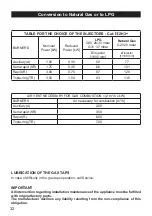
TABLE FOR THE CHOICE OF THE INJECTORS - Cat: 

II

 2H3+

BURNERS

Nominal 

Power [kW]

Reduced 

Power [kW]

LPG

G30  28-30 mbar

G31  37 mbar

Natural Gas

G20 20 mbar

Ø injector

[1/100 mm]

Ø injector

[1/100 mm]

Auxiliary (A)

1,00

0,30

50

77

Semi-rapid (SR)

1,75

0,45

66

101

Rapid (R)

3,00

0,75

87

129

Triple-ring (TR)

3,50

1,50

93

135

AIR VENT NECESSARY FOR GAS COMBUSTION = (2 m

3

/h x kW)

BURNERS

Air necessary for combustion [m

3

/h]

Auxiliary (A)

2,00

Semi-rapid (SR)

3,50

Rapid (R)

6,00

Triple-ring (TR)

7,00

LUBRICATION OF THE GAS TAPS

In case of difficulty in the gas taps operation, call Service.

IMPORTANT

All intervention regarding installation maintenance of the appliance must be fulfilled 

with original factory parts.

The manufacturer declines any liability resulting from the non-compliance of this 

obligation.

Conversion to Natural Gas or to LPG

Summary of Contents for ELSC 90 DF

Page 1: ...ly H O M E A P P L I A N C E S 100 ELBAQUALITY MADE IN ITALY Instructions for the use Installation advices DUAL FUEL COOKER model ELSC 90 DF GB Before operating this cooker please read these instructions carefully ...

Page 2: ...2 ...

Page 3: ...r that is for cooking foodstuffs Any other form of usage is to be considered as inappropriate and therefore dangerous The manufacturer declines all responsibility in the event of damage caused by improper incorrect or illogical use of the appliance DECLARATION OF CE CONFORMITY This cooker has been designed constructed and marketed in compliance with Safety requirements of the Gas Directive 2009 14...

Page 4: ...accordance to health and environmental protection regulations ensuring in particular that all potentially hazardous parts be made harmless especially in relation to children who could play with unused appliances After use ensure that the knobs are in the off position Household appliances are not intended to be played with by children Keep children away from the cooker during use Children or person...

Page 5: ...operty cau sed by incorrect or improper use of the appliance The various components of the appliance are recyclable Dispose of them in accor dance with the regulations in force in your country If the appliance is to be scrapped remove the power cord Always use oven gloves when removing the shelves and food trays from the oven whilst hot Do not hang towels dishcloths or other items on the cooker or...

Page 6: ... if and when the flame should accidentally go out CAUTION Gas appliances produce heat and humidity in the environment in which they are installed Ensure that the cooking area is well ventilated by opening the natural ventilation grilles or by installing an extractor hood connected to an outlet duct CAUTION If the appliance is used for a prolonged time it may be necessary to provide further ventila...

Page 7: ...l knob 7 Front right burner control knob Pilot lamp 8 Oven temperature indicator light 2 1 4 3 5 7 6 8 Fig 2 1 CONTROL PANEL 2 Please note This appliance incorporates a safety cooling fan which you will hear operating whenever the oven or grill are in use The cooling fan may also operate when the oven is switched off This fan is to reduce the external temperature of the appliance and cool the inte...

Page 8: ...ts to the symbols printed on the panel achieves the following functions symbol closed valve symbol maximum aperture or flow symbol minimum aperture or flow The maximum aperture position per mits rapid boiling of liquids whereas the minimum aperture position allows slower warming of food or maintaining boiling conditions of liquids To reduce the gas flow to minimum rotate the knob further anti cloc...

Page 9: ...since the capacity of heat absorption of a liquid mass depends on the volume and the surface of the pot LIGHTING THE BURNERS To ignite the burner the following instruc tions are to be followed 1 Press in the corresponding knob and turn counter clockwise fig 3 2 to the full flame position marked by the symbol fig 3 1 and hold the knob in unt il the flame has been lit In the case of a mains failure ...

Page 10: ...PERATING PRINCIPLES Heating and cooking in the FAN oven are obtained in the following ways a by forced convection A fan sucks in the air contained in the oven muffle which sends it through the circular heating element and then sends it back through the muffle Before the hot air is sucked back again by the fan to repeat the descri bed cycle it envelops the food in the oven provoking a complete and ...

Page 11: ...oven temperature FUNCTION SELECTOR KNOB Fig 4 1 Rotate the knob clockwise to set the oven for one of the following functions OVEN LIGHT By setting the knob to this position only the oven light comes on It remains on in all the cooking modes DEFROSTING FROZEN FOODS Only the oven fan comes on Use with the thermostat knob set to 0 other positions have no effect The food is thawed by ventilation witho...

Page 12: ...r example lasagne lamb roast beef whole fish etc GRILLING The infrared grill element comes on The heat is dispersed by radiation Set the thermostat knob to between 50 and 200 C Always grill with the oven door closed For cooking hints see the chapter USE OF THE GRILL Recommended for Intense grilling browning cooking au gratin and toasting etc Do not grill for longer than 30 minutes at any one time ...

Page 13: ...MULTANEOUS COOKING OF DIFFERENT FOODS The FAN consents a simultaneous heterogeneous cooking of different foods Different fo ods such as fish cake and meat can be cooked together without mixing the smells and fla vors together This is possible since the fats and vapors are oxidized while passing through the electrical element and therefore are not deposited onto the foods The only precaution to fol...

Page 14: ...s 150 C 300 F Cool or slow oven Stews casseroles braising rich fruit cakes eg Dundee 160 C 170 C 320 F 338 F Warm oven Biscuits Low temperature roasting rich plain cakes eg Madeira cake 180 C 356 F Moderate oven Plain cakes eg Victoria sandwich meat pies 190 C 374 F Fairly hot oven Small cakes savoury flans fish 200 C 392 F Hot oven Plain cakes and buns swiss rolls fruit pies High temp roasting 21...

Page 15: ... and registered person in accordance with the relevant Standards Attention The appliance gets very hot mainly around the cooking areas It is very important that children are not left alone in the kitchen when you are cooking AFTER SALES SERVICE Should you require to book a service call telephone 0870 5425425 For product information and advise telephone 0113 2793520 ...

Page 16: ...o be touched and may contain sharp or rough edges that may cause injury ENAMELLED PARTS All the enamelled parts must be cleaned with a sponge and soapy water or other non abrasive products Dry preferably with a microfibre or soft cloth Acidic substances like lemon juice tomato sauce vinegar etc can damage the ena mel if left too long STAINLESS STEEL ALUMINIUM PARTS PAINTED AND SILK SCRE EN PRINTED...

Page 17: ...b Note Oven bulb replacement is not cove red by your guarantee BURNERS They can be removed and washed with soapy water only They will remain always perfect if cleaned with products used for silverware After cleaning or wash check that burner caps and burner heads are dry before pla cing them in the respective housings Check that the electrode S figs 6 1 6 3 next to each burner is always clean to e...

Page 18: ...18 S F C T Fig 6 1 Fig 6 2 A B S T Fig 6 3 Fig 6 4 Fig 6 5 ...

Page 19: ...hich stops it sliding out faces the inside of the oven fig 6 7 To dismantle operate in reverse order OVEN TRAY The oven tray must be correctly placed on its wire support then inserted into the side runners fig 6 8 OVEN FLOOR The oven floor F fig 6 8 can be easily removed to facilitate cleaning Remember to replace the floor correctly afterwards Be careful not to confuse the tray L with the oven flo...

Page 20: ...ammable material in the oven or in the storage compartment Do not use harsh abrasive cleaners or sharp metal scrapers to clean the oven door glass since they can scratch the surface which may result in shattering of the glass STORAGE COMPARTMENT The storage compartment is accessible through the pivoting panel fig 6 10 Fig 6 10 Fig 6 9 ...

Page 21: ... 6 12a Attach the retaining rings to the ho oks on the left and right hinges fig 6 12b Hold the door as shown in fig 6 11 Gently close the door and withdraw the lower hinge pins from their loca tion fig 6 12c Withdraw the upper hinge pins from their location fig 6 12d Rest the door on a soft surface To replace the door repeat the above steps in reverse order ...

Page 22: ...ny manufacturer s warranty The appliance must be installed in compliance with regulations in force in your country and in observation of the manufacturer s instructions Always disconnect the appliance from the electrical supply before carrying out any maintenance operations or repairs Some appliances are supplied with a protective film on steel and aluminium parts This film must be removed before ...

Page 23: ... the furniture The furniture walls adjacent to the cooker must be made of material resistant to heat The veneered synthetical material and the glue used must be resistant to a temperature of 90 C in order to avoid ungluing or deformations The cooker may be located in a kitchen a kitchen diner or bed sitting room but not in a room containing a bath or shower Curtains must not be fitted immediately ...

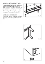
Page 24: ...he rear of the cooker on a piece of the polystyrene packaging exposing the base for the fitting of the feet Fit the 4 legs by screwing them tight into the support base as shown in figure 7 3 LEVELLING THE COOKER The cooker may be levelled by screwing the lower ends of the feet IN or OUT fig 7 4 Fig 7 4 Fig 7 3 Fig 7 2 ...

Page 25: ...out this manoeuvre to prevent damage to the adjustable feet fig 7 5 WARNING Be carefull do not lift the cooker by the door handle when raising to the upright position fig 7 6 WARNING When moving cooker to its final posi tion DO NOT DRAG fig 7 7 Lift feet clear of floor fig 7 5 Fig 7 7 Fig 7 6 Fig 7 5 ...

Page 26: ... STABILITY BRACKET OR STABILITY CHAIN Due to varying site and installation requirements stability devices are not supplied with this appliance It is therefore the responsibility of the suitably qualified and registered installer to ensure that a suitable stability device for the type of installation is fitted to the appliance as shown in figures 7 8a or 7 8b below This can be purchased from most p...

Page 27: ...tside air in which case no permanent ventilation is required For rooms with a volume greater than 10 m3 no permanent ventilation is required NB Regardless of room size all rooms containing the appliance must have direct access to the outside air via an openable window or equivalent Where there are other fuel burning appliances in the same room BS 5440 2 2000 should be consulted to determine the co...

Page 28: ...ution under the above quoted regulation GAS INSTALLATION REQUIREMENTS Important The walls adjacent to the cooker must be of heat resistant material Before installation make sure that the local distribution conditions gas type and pressure and the adjustment of this appliance are compatible The applian ce adjustment conditions are given on the plate or the label This appliance must be installed and...

Page 29: ...chnical knowledge of electricity should install the appliance He should observe the Regulations and Codes of Practice governing such installation of gas appliances Note It is recommended that the gas connection to the appliance is installed with a flexible connecting tube made to BS5386 Notes Flexible hoses can be used where the sited ambient temperature of the hose does not exceed 70 C These hose...

Page 30: ...s fig 8 2 The unused end inlet pipe must be closed with the plug interposing the gasket After connecting to the mains check that the coupling are correctly sealed using soapy solution but never a flame Gasket Fitting the 1 2 BSP male connector The male connector is supplied with the appliance in a separate kit 1 2 BSP male Fitting the plug on the inlet pipe terminal not used Cooker manifold Right ...

Page 31: ...31 Rear wall 700 mm Suggested area for gas mains connection 200 mm IMPORTANT PRESCRIPTIONS FOR GAS CONNECTION Fig 8 3 ...

Page 32: ...5 AIR VENT NECESSARY FOR GAS COMBUSTION 2 m3 h x kW BURNERS Air necessary for combustion m3 h Auxiliary A 2 00 Semi rapid SR 3 50 Rapid R 6 00 Triple ring TR 7 00 LUBRICATION OF THE GAS TAPS In case of difficulty in the gas taps operation call Service IMPORTANT All intervention regarding installation maintenance of the appliance must be fulfilled with original factory parts The manufacturer declin...

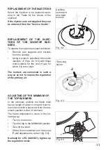
Page 33: ... F Fig 8 6 REPLACEMENT OF THE INJECTORS Select the injectors to be replaced accor ding to the Table for the choice of the injectors If the injectors are not supplied they can be obtained from the Service Centre REPLACEMENT OF THE INJEC TORS OF THE COOKTOP BUR NERS To replace the injectors proceed as follows Remove pan supports and burners from the cooktop Using a wrench substitute the nozzle injec...

Page 34: ... intervention on the electrical parts the appliance must be di sconnected from the network WARNING ELECTRICITY CAN BE EXTREMELY DANGEROUS THIS APPLIANCE MUST BE EARTHED ELECTRICAL FEEDER CABLE CONNECTION The operations must be executed by a qualified technician To connect the supply cable Remove the screws securing the cover A on the rear of the cooker fig 9 1 Feed the supply cable through the cab...

Page 35: ...itch must be provided no further than 2 metres from the appliance to the electrical supply The appliance should be connected to a DOUBLE POLE SWITCHED FUSED SPUR OUTLET We recommend that the appliance is connected by a suitably qualified person who will comply with the IEE and local regulation ...

Page 36: ...es due to printing or transcription errors in the present booklet The manufacturer reserves the right to make all modifications to its products deemed necessary for manufacturer commercial reasons at any moment and without prior notice without jeopardising the essential functional and safety characteristics of the appliances ...

Reviews: