ES30 Dual Stereo Panner
ELBY Designs - Laurie Biddulph
9 Follan Close, Kariong, NSW 2250, Australia
2 of 3
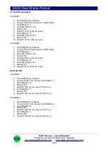
Construction of the ES30 requires the assembly of 3 boards:-
Column 1 - ES30 Channel PCB (
) (
)
Column 2 - ES30 Channel PCB (
) (
)
Back Board - ES30 Main PCB (
)
Constructors should refer to the PCB Overlays for any
specific comments regarding the board assembly, the
Materials
for the current value of all components and
for general PCB assembly
guidelines.
1. Assemble the 4 Carrier Board assemblies (
)
2. The 2x [GAIN CV] assemblies need to have R124
fitted to the underside of the board as shown here
(
)
3. Fit all components to the boards following normal
assembly guidelines except for the sub-assemblies
4. Fit 2x sub-assemblies to the Column 1 board but do
not solder
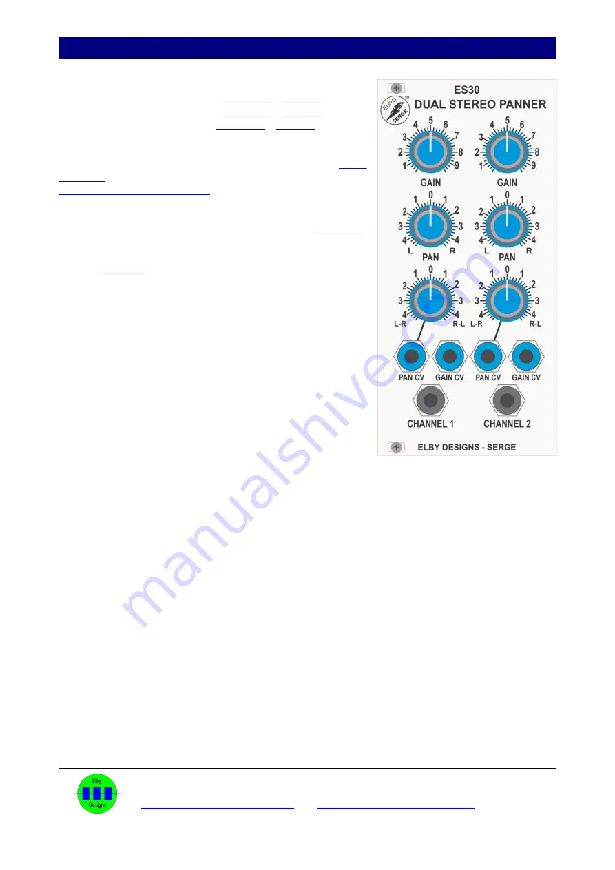
5. Offer the assembly up to the front panel and secure
using the supplied nuts
6. Solder the sub-assemblies in to place
7. Repeat for the Column 2 board
8. Mount the back board ensuring it is correctly aligned
with the IDC headers
Calibration
Equipment required:
1. 50Hz 5VDC p-p sawtooth wave
2. 1kHz 5VAC p-p triangle wave
Calibration procedure:
If the ES30 is installed in an ES31 module then set [ATTENUATION] to maximum (‘0dB’),
otherwise temporarily add a wire link from …. to +12V


