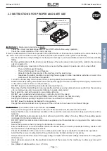
ENG man E1-MIA 00
E1-MIA Radio Remote Control
- Page 4 -
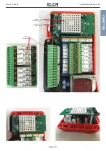
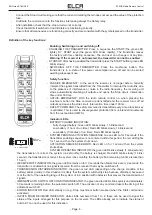
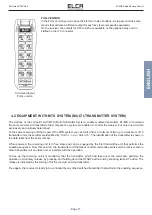
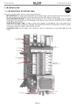
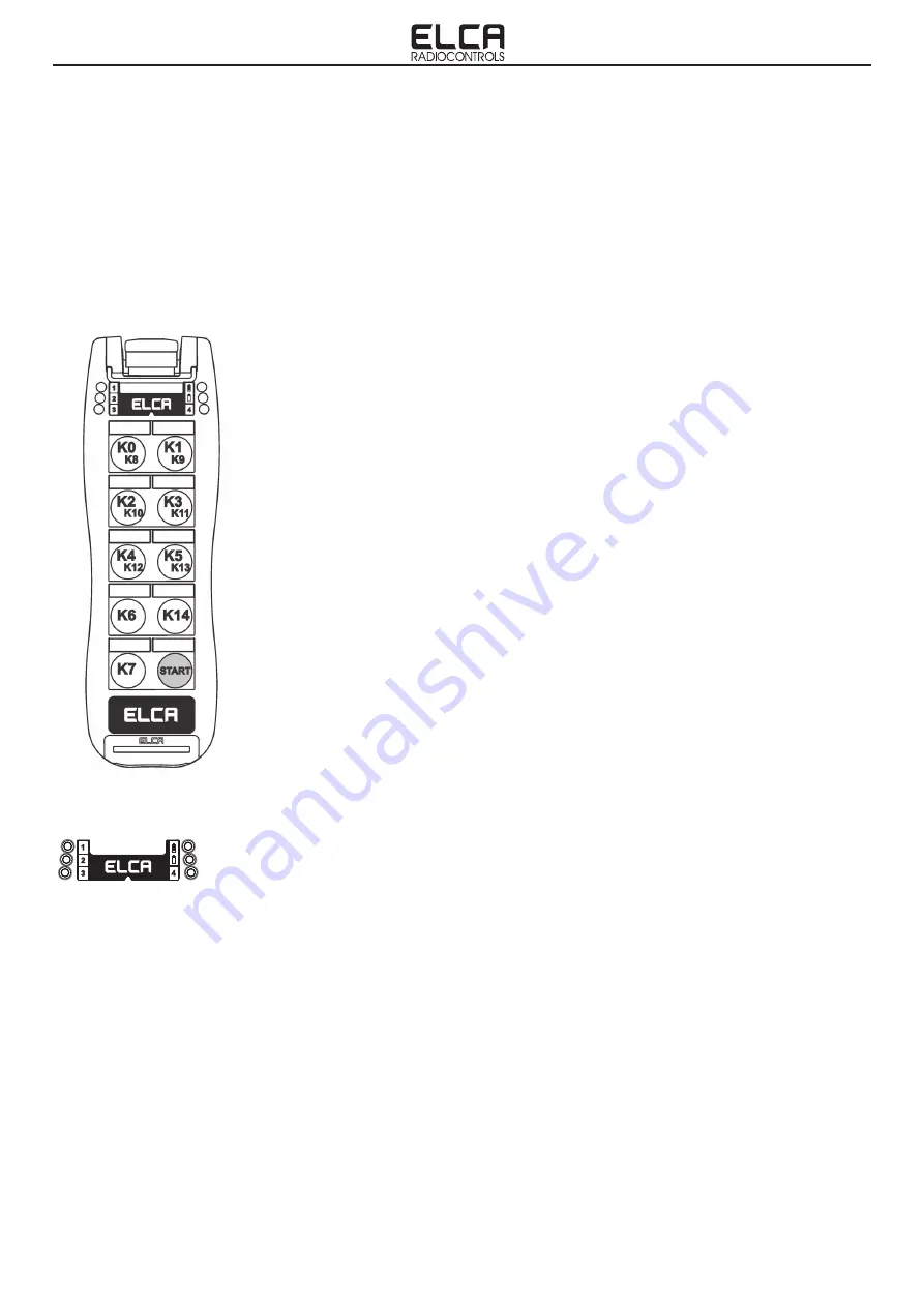
Spia ROSSA
Spia VERDE
1, 2, 3, 4 Spie Bianche
-
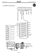
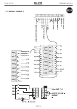
Connect the Stop circuit making sure that the current circulating therein does not exceed the value of the protection
fuse.
-
Distribute the common wire to the functions interposing always the Safety relay.
-
After installation check that the stop circuit works correctly.
-
Check that all limit switched or load limiters are functioning correctly.
-
Ensure that all manoeuvres are functioning correctly and are consistent with the symbols placed on the transmitter.
Definition of the key functions:
Enabling, Switching on and switching off:
-
ENABLING THE TRANSMITTER. Press in sequence the START (the green LED
lights), K7, START keys (the green LED blinks rapidly). The transmitter leaves
the factory with this enabling sequence; The end user can change it at any time.
Warning: If the receiver is not powered, the transmitter can not be enabled.
-
START-UP. After having enabled the transmitter press the START button (green LED
blinks slowly).
-
SWITCHING OFF THE TRANSMITTER. Press the mushroom button. The
transmitter is in a state of low power consumption when off and can be stored
awaiting subsequent use.
Safety function.
-
PASSIVE EMERGENCY: In the event the receiver is no longer able to correctly
interpret the signals transmitted from the Transmitter to interrupt the radio link, due
to the presence of interference or noise in the radio frequency, the receiving unit
stops automatically disabling all outputs and opens the Stop circuit. Intervention
time under 500 ms.
-
ACTIVE EMERGENCY: With the radio remote control on, when pressing the
mushroom button the Stop command is transmitted and the receiver turns off all
outputs and opens the stop circuit. Intervention time under 100 ms.
-
SAFETY COMMAND: The safety command is transmitted every time a function key
is activated. This is used to ensure greater protection from unintended movements
from the rest position (UMFS).
Indicator LEDs.
-
BATTERY CHARGE INDICATION:
-
Fully charged battery: Green LED blinks slowly, 1 blink/second
-
Low battery (1 hour of run time): Red LED blinks slowly, 1 blink/second
-
Low battery (5 minutes of run time): Red LED blinks rapidly.
-
SYSTEM PENDING ACTIVATION SEQUENCE: Green LED on for 5 seconds: if the
transmitter enabling sequence is not entered within this period, the red LED lights
for 1 second, then the system shuts down.
-
ACTIVATION SEQUENCE ERROR: Red LED on for 1 second then the system
shuts down.
-
SYSTEM OPERATING INDICATOR: the green LED blinks slowly (1 blink/second):
RED led
GREEN led
1, 2, 3, 4 white LEDs
the transmission is correct, the system runs smoothly, the battery is charged. Red LED blinks slowly (1 blink/
second): the transmission is correct, the system runs smoothly, the battery is flat (remaining run time is less than
1 hour).
-
RECEIVER OFF INDICATOR: the green LED remains on for 10 seconds then blinks twice every 2 seconds: the
transmitter is enabled but no signal is received from the receiver that may be switched off.
-
TRANSMISSION DISTURBED INDICATOR: the green or red LED (depending on the charge condition of the
battery) blinks quickly. In this situation it is likely that the system will shortly stop because disturbed, because it
is at the limit of the operating range of the system or in a position with obstacles that prevent the transmission of
signals.
-
IMMINENT AUTO SWITCH OFF CONDITION INDICATOR: the green and red LEDs blink quickly and alternately:
30 seconds remaining before the automatic switch off. The activation of any command resets the timing of the
automatic switch off.
-
ERROR INDICATOR: Red LED steady on (e.g. Stop mushroom button pressed when the Start command is
activated).
-
INPUTS FROM RECEIVER INDICATOR: white LEDs numbered from 1 to 4; these can be used to signal the
status of the inputs arranged for this purpose on the receiver. The LEDs already set to indicate the status of
button K7 can not be used for this indication.

