
ENG man E1-MIA 00
E1-MIA Radio Remote Control
- Page 10 -
Model ............................................................................................................. ELCA-CLIP Vac
Supply voltage ..................................................................................100 - 240 V
[
50/60 Hz
Absorbed current .............................................................................................................0.2 A
Rated output voltage .................................................................................................... 5 V
]
Rated output current ...........................................................................................................1 A
Full recharging time ........................................................................................approx 4 hours
Charge time for 2 hours of run time .........................................................approx. 20 minutes
Working temperature ...........................................................................from -25 °C to +55 °C
Protection degree ........................................................................................................... IP40
Electric plug model ...................................................................Europlug Type C (EEC 7/16)
Cable length .............................................................................................................2 metres
Weight ............................................................................................................................100 g
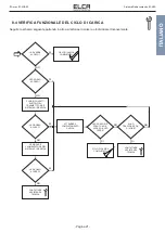
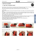
3.4 CHARGING SYSTEM FEATURES
The AT E1-MIA transmitting unit contains an internal identification code card that allows the receiving unit the identification
of the unit that has transmitted the command. In this way any other device, different or the same type, that is transmitting
on the same frequency can not in any way replace the control of the machine to which the system is connected. Any radio
transmissions on the same working frequency as the transmitter or any radio frequency disturbances can in the worst
case switch off the receiver with all outputs disabled (See description of receiving unit operations).
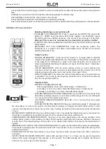
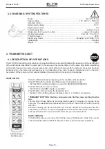
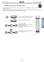
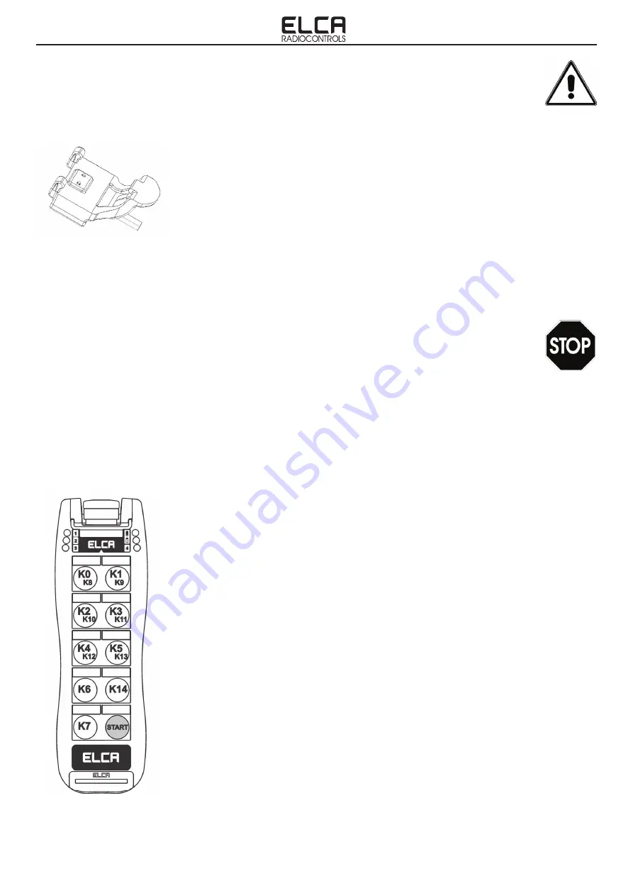
START BUTTON
.
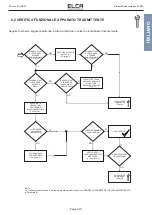
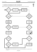
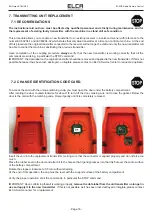
4.1 DESCRIPTION OF OPERATIONS
4. TRANSMITTING UNIT
Performs different functions depending on the condition of the transmitter.
Press START with the transmitter off (low power consumption mode):
- the transmitter reactivates waiting to receive the ENABLING SEQUENCE.
Press START with the receiver active:
- the START and ALARM outputs are activated.
Press START + K0 butto when the transmitter is off:
- the status of the battery gharge is displayed. Leds 1, 2, 3 light on in sequence.
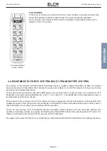
“COMMAND” BUTTONS, 8 buttons, arranged on the first four rows, starting from the
top.
The first click of these buttons is interlocked with respect to the button on the side of the
same row. The interlocked commands are then K0 with K1, K2 with K3, K4 with K5 and K6
with K14.
Example: Pressing the K0 keys and then K1 will only activate the command of the first
pressed key, that is K0. The same thing applies to the second click and then following the
example with active K0, the second click command you can activate is K8.
BASIC VERSION.
In the BASE version you can have the first three rows of buttons with 2-step. The second-
click commands activate a different output for each key (second speeds separated).
Command layout
BASE version


