background image

ENG man E1-MIA 00


E1-MIA Radio Remote Control

- Page 17 -

ENGLISH

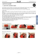
Any equipment replacing the card with the identifi cation code must be enabled for its use by the identifi cation code 

acquisition procedure.

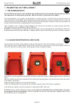
At the fi rst power on the transmitter, the red and green LEDs are lit up for 3 seconds at the same time, and then it remains 

awaiting command inputs with the green fl ashing light fl ashing slowly.

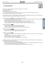
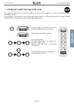
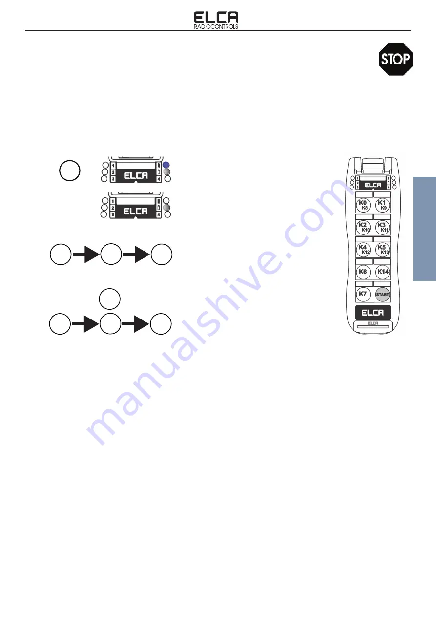
7.3 ENABLING IDENTIFICATION CODE CARD

START

At the fi rst press of the START key, the red 

and green LEDs light up for 3 seconds.

Enter the PIN CODE.

The default PIN CODE is the sequence of 

START, K0, START keys. 

The green LED lights up for 1 second and 

then turns off.

Then the Green LED blinking slowly.

Press Start and then enter the PIN CODE.

The transmitter is now on.

K7

START

START

K7

START

START

START

Summary of Contents for AT E1-MIA

Page 1: ...l radio remote control AT E1 MIA Apparato trasmittente Transmitting Unit ELCA S r l Via del Commercio 7 b 36065 Mussolente VI ITALY www elcaradio com tel 39 0424 578500 fax 39 0424 578520 MULTI man E1 MIA 00 0408MA000160 Manuale d uso User manual ...

Page 2: ......

Page 3: ...Manuale d uso User manual ENGLISH ITALIANO ...

Page 4: ......

Page 5: ...RATTERISTICHE UNITA RICEVENTE 9 3 4 CARATTERISTICHE SISTEMA DI RICARICA 10 4 UNITA TRASMITTENTE 10 4 1 DESCRIZIONE DEL FUNZIONAMENTO 10 4 2 APPARATI CON SISTEMA MTS MULTI TRANSMITTER SYSTEM 11 5 UNITA RICEVENTE 12 5 1 DESCRIZIONE DEL FUNZIONAMENTO 12 5 2 ESEMPIO DI CABLAGGIO 14 6 CARICABATTERIE 15 6 1 USO DEL CARICABATTERIE 15 7 SOSTITUZIONE DELL UNITA TRASMITTENTE 16 7 1 RACCOMANDAZIONI 16 7 2 SO...

Page 6: ...ITA man E1 MIA 00 Sistema Radiocomando E1 MIA Pagina II ...

Page 7: ...ati al manuale che devono essere considerati come parte integrante del manuale stesso Contattare ELCA nel caso in cui vi siano istruzioni avvertenze o indicazioni che risultassero poco chiare Le informazioni fornite da ELCA in questo manuale sono da reputarsi accurate ed attendibili comunque l azienda non può essere ritenuta responsabile per omissioni o errori riscontrati Questa edizione è stata a...

Page 8: ...arsi dove è possibile controllare al meglio i movimenti della stessa e di scegliere una posizione di lavoro più sicura in tutta libertà Il Radiocomando è realizzato in modo da utilizzare al momento dell accensione una frequenza libera da interferenze in modo tale da non disturbare altri apparati presenti nelle vicinanze e viceversa non esserne disturbato Qualsiasi comando trasmesso contiene al suo...

Page 9: ... le unità con getti d acqua ma utilizzare solamente un panno umido Non utilizzarlo all interno di ambienti schermati ad es all interno del tamburo della betoniera Caricare le batterie in ambienti che non siano troppo caldi troppo freddi troppo umidi o polverosi Mantenere le batterie in uno stato mediamente carico permette di allungarne la vita utile NON lasciare le batterie scariche per lunghi per...

Page 10: ...de il LED verde tasto K7 START il LED verde lampeggia velocemente Il trasmettitore esce dalla fabbrica con questa sequenza di abilitazione l utente finale la può modificare in qualsiasi momento Attenzione Se il ricevitore non è alimentato il trasmettitore non potrà essere abilitato MESSA IN MARCIA Dopo aver abilitato l unità trasmittente premere il pulsante START il LED verde lampeggia lentamente ...

Page 11: ...ILITAZIONE PREDEFINITA Accedere al menu di Programmazione vedi ACCEDERE AL MENU DI PROGRAMMAZIONE 1 Premere il tasto K1 il LED verde esegue 2 lampeggi al secondo 2 Confermare la programmazione premendo contemporaneamente i tasti K7 START e K1 per alcuni secondi IMPOSTAZIONE SEQUENZA DI ABILITAZIONE PERSONALIZZATA Accedere al menu di Programmazione vedi ACCEDERE AL MENU DI PROGRAMMAZIONE 1 Premere ...

Page 12: ...lle correnti che circolano nei relè di STOP e di SAFETY in modo che non superino mai i valori consentiti di 4A Il contatto del relè SAFETY deve essere collegato in serie al comune dei comandi di movimento quando sia richiesta la protezione di sicurezza rispetto all attivazione involontaria del comando con attuatore a riposo UMFS unintended movement from standstill PL c E IMPERATIVO utilizzare semp...

Page 13: ...da effettuare una volta alla settimana Pulire con un panno umido il trasmettitore e verificarne l integrità Pulire i contatti di ricarica prima di procedere all operazione di ricarica Verificare l integrità dell unità ricevente Il guscio non deve presentare crepe Controlli da effettuare una volta al mese Pulire con un panno umido l unità ricevente e valutarne l integrità Pulire i contatti dell ali...

Page 14: ... non è responsabile per l eventuale fermo macchina dovendo l utente avere per ogni macchina la possibilità di utilizzarla con un comando manuale o a cavo Per eventuali controversie è competente il Foro di Vicenza 2 7 GARANZIA Il Radiocomando a fine vita deve essere smaltito presso il servizio recupero differenziato dei rifiuti SMALTIMENTO DELLE BATTERIE Direttiva 2006 66 CE e successive modifiche ...

Page 15: ...15 W Potenza di emissione R F 10 mW ERP Autonomia con batteria carica a 20 C circa 20 ore Autonomia dopo prima modalità di avviso batteria scarica circa 60 minuti Autonomia dopo seconda modalità di avviso batteria scarica 5 minuti Grado di protezione IP65 Dimensioni 235x72x65 mm Peso 390 g Modello AR E1 FLEXI A Modulo radio ricetrasmittente MR32EL Antenna incorporata Alimentazione in corrente alte...

Page 16: ...funzionamento unità ricevente 4 1 DESCRIZIONE DEL FUNZIONAMENTO 4 UNITA TRASMITTENTE TASTO START Svolge diverse funzioni a seconda dello stato in cui si trova il trasmettitore Premere START con trasmettitore spento modalità a bassissimo consumo il trasmettitore si risveglia e rimane in attesa di ricevere la SEQUENZA DI ABILITAZIONE Premere START con l unità ricevente attiva si attiva il relè START...

Page 17: ... abilitazione Da questo momento in poi l unità trasmittente che prende il controllo comanda in esclusiva l unità ricevente e nessuna altra unità trasmittente può subentrare od interferire sul funzionamento Per liberare l unità ricevente è obbligatorio che la trasmittente che ha assunto il comando esegua l operazione di rilascio volontario mantenendo premuto START e premendo due volte il tasto K7 I...

Page 18: ... ID CON IL CODICE IDENTIFICATIVO Come si evince dal nome contiene il codice identificativo del sistema che è univoco Questo codice permette al sistema di riconoscere i segnali trasmessi dal trasmettitore a cui è accoppiato In questa scheda vengono anche memorizzati i dati funzionali del sistema SCHEDA ESPANSIONE Scheda che permette di espandere le funzionalita del sistema in modo da ottenere otto ...

Page 19: ...ITA man E1 MIA 00 Sistema Radiocomando E1 MIA Pagina 13 ITALIANO MODULO RADIO RICETRASMITTENTE SCHEDA CODICE IDENTIFICATIVO SCHEDA ESPANSIONE ESPANSIONE ESPANSIONE ...

Page 20: ...ITA man E1 MIA 00 Sistema Radiocomando E1 MIA Pagina 14 5 2 ESEMPIO DI CABLAGGIO 0Vac SUPPLY 48 55 110 230Vac SUPPLY V 10 55 Vac dc IN1 IN2 IN3 IN4 0V 48V 55V 110V 230V IN1 IN2 IN3 IN4 RIF ...

Page 21: ... temperature ammesse Il processo di ricarica completo dura circa 4 ore Se la batteria è agganciata all unità trasmittente con unità spenta premendo e mantenendo premuto il tasto START assieme al tasto in alto a sinistra dopo 3 doppi lampeggi del LED rosso i LED bianchi 1 2 3 si accendono progressivamente a seconda dello stato di carica della batteria solo LED 3 acceso indica che la batteria è scar...

Page 22: ... particolare dello STOP IMPORTANTE rimuovere la targa dati dalla trasmittente non più utilizzabile ed applicarla sulla nuova Nel caso non sia possibile perchè persa distrutta o illeggibile contattare un Centro Assistenza ELCA per richiederne il rifacimento 7 SOSTITUZIONE DELL UNITA TRASMITTENTE Per accedere alla scheda con il codice univoco di abbinamento è necessario aprire lo sportello posto sot...

Page 23: ... poi rimane in attesa di input comandi con la spia verde che lampeggia lentamente 7 3 PROCEDURA DI ACQUISIZIONE CODICE IDENTIFICATIVO START Alla prima pressione del tasto START i LED rosso e Verde si accendono per 3 secondi Inserire il PIN CODE Se non è stato modificato dall utente il PIN CODE di default è la sequenza di tasti START K0 START Il LED verde si accende fisso per 1 secondo e poi si spe...

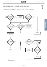
Page 24: ...i siano altri impianti simili o fonti di disturbo come ponti radio o apparati di trasmissione Spegnere e riaccendere il trasmettitore LED verde fisso e LED rosso lampeggia 2 volte ogni 2 secondi ERRORE SUL RICEVITORE Spegnere e riaccendere l apparato trasmittente Se non si risolve contattare l assistenza tecnica IMPIANTO NON CORRETTAMENTE INSTALLATO Verificare la corretta installazione dell impian...

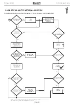
Page 25: ...FUNZIONA SI FINE VERIFICA NO SI SI NO SI CONTATTARE ASSISTENZA TECNICA SI NO FACENDO START IL LED VERDE SI ACCENDE LAMPEGGIANTE O FISSO FACENDO START IL LED VERDE SI ACCENDE FISSO FACENDO START IL LED VERDE LAMPEGGIA E IL ROSSO E FISSO TRASMITTENTE NON ABBINATO AD ALCUN RICEVITORE ESEGUIRE COUPLING v Cap 7 NO ESEGUIRE LA SEQUENZA DI ABILITAZIONE start G start di default E POI START IL LED VERDE LA...

Page 26: ...ATTIVATI SI ACCENDONO SI E PRESENTE TENSIONE SUI MORSETTI DI ALIMENTAZIONE ALL INTERNO DEL RICEVITORE SI NO VERIFICARE CHE IL CAVO DI ALIMENTAZIONE SIA CORRETTAMENTE COLLEGATO FORNIRE ALIMENTAZIONE IL RADIOCOMANDO FUNZIONA SI NO FINE VERIFICA NO IL RADIOCOMANDO FUNZIONA SI NO CONTATTARE ASSISTENZA TECNICA CONTATTARE ASSISTENZA TECNICA NO COLLEGAMENTO RADIO ASSENTE v Paragrafo 8 1 SULLA TRASMITTENT...

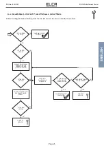
Page 27: ... PULIRE I CONTATTI ELETTRICI SU TRASMETTITORE E SISTEMA DI RICARICA LED ROSSO ACCESO NO NO CONTATTARE ASSISTENZA TECNICA LED ROSSO SI E SPENTO E SI E ACCESO IL LED VERDE SI CICLO DI CARICA COMPLETATO NO SI SI VERIFICARE L ALIMENTATORE DEL SISTEMA DI RICARICA LED ROSSO ACCESO NO SI ATTENDERE COMPLETAMENTO CARICA SONO TRASCORSE PIU DI 4 ORE SI NO CONTATTARE ASSISTENZA TECNICA LED VERDE ACCESO SI NO ...

Page 28: ...UNIT FEATURES 9 3 3 RECEIVING UNIT FEATURES 9 3 4 CHARGING SYSTEM FEATURES 10 4 TRANSMITTING UNIT 10 4 1 DESCRIPTION OF OPERATIONS 10 4 2 EQUIPMENT WITH MTS SYSTEM MULTI TRANSMITTER SYSTEM 11 5 RECEIVING UNIT 12 5 1 DESCRIPTION OF OPERATIONS 12 5 2 WIRING EXAMPLE 13 6 BATTERY CHARGER 14 6 1 BATTERY CHARGER USAGE 14 7 TRANSMITTING UNIT REPLACEMENT 15 7 1 ATTENTION 15 7 2 COUPLING PROCEDURE 15 7 3 C...

Page 29: ...ENG man E1 MIA 00 E1 MIA Radio Remote Control Page II ...

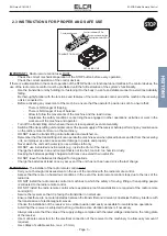
Page 30: ...onsidered as an integral part of the manual Contact ELCA in the event there are instructions warnings or indications which may prove to be unclear The information provided by ELCA in this manual are regarded as accurate and reliable however the company can not be held responsible for omissions or errors This updated edition incorporates suggestions from our Customers to provide an effective tool s...

Page 31: ...freedom The radio remote control is designed in order to be used when an interference free frequency is activated so as not to disturb other devices in the vicinity and vice versa not be disturbed Any command transmitted contains a unique code that can not be changed which makes the activation of manoeuvres by different transmitters of any brand or model impossible At the time of going to print th...

Page 32: ...nly DO NOT use in shielded environments e g inside the drum of the mixer Charge the batteries in an environment that is not too hot too cold too humid or dusty Keeping the batteries partially charged at all times can extend their useful life DO NOT leave the batteries discharged for long periods Charge the batteries at least once a year even if the unit has not been used since the last charge IMPO...

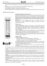
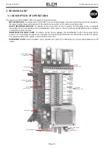
Page 33: ...his is used to ensure greater protection from unintended movements from the rest position UMFS Indicator LEDs BATTERY CHARGE INDICATION Fully charged battery Green LED blinks slowly 1 blink second Low battery 1 hour of run time Red LED blinks slowly 1 blink second Low battery 5 minutes of run time Red LED blinks rapidly SYSTEM PENDING ACTIVATION SEQUENCE Green LED on for 5 seconds if the transmitt...

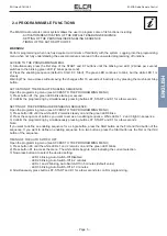
Page 34: ...he programming by simultaneously pressing buttons K7 START and K1 for a few seconds SETTING OF THE PERSONALISED ENABLING SEQUENCE Open the programming menu see ACCESS TO THE PROGRAMMING MENU 1 Press button K0 until the white LED 2 remains steady on and the green LED blinks 2 Press the sequence of buttons you want to set as an enabling sequence White LEDs 1 2 and 3 light in sequence 3 Confirm the p...

Page 35: ...ntrol relays Pay attention to the current in the STOP and SAFETY relays so that it never exceeds the permitted value of 4A The SAFETY relay contact must be connected in series with the common wire of the movement command when the safety protection is required in relation to the involuntary activation of the control with actuator at rest UMFS unintended movement from standstill PL c IT IS IMPERATIV...

Page 36: ...have cracks or holes Controls to be performed weekly Clean the transmitter with a damp cloth and verify its integrity Clean the charge contacts before proceeding to recharge Check the integrity of the receiving unit The casing should not have cracks Controls to be performed monthly Clean the receiving unit with a damp cloth and assess its integrity Clean the contacts of the charging system s power...

Page 37: ... to property or persons ELCA shall not be liable for machine down time and it is the user s responsibility to provide manual or wire control for each machine Any disputes shall be submitted to the Court of Vicenza Italy 2 7 WARRANTY The radio remote control must be delivered to separate collection at end of life DISPOSAL OF BATTERIES Directive 2006 66 EC and subsequent amendments Batteries may rel...

Page 38: ...bsorbed power 0 15 W RF effective radiated power 10 mW ERP Run time with fully charged battery at 20 C approximately 20 hours Run time after the first low battery warning approx 60 minutes Run time after the second low battery warning 5 minutes Protection degree IP65 Dimensions 235x72x65 mm Weight 390 g Model AR E1 FLEXI A Radio transceiver module MR32EL Incorporated antenna AC power supply 48 55 ...

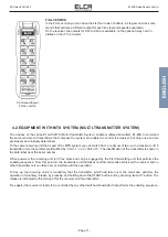
Page 39: ...nit operations START BUTTON 4 1 DESCRIPTION OF OPERATIONS 4 TRANSMITTING UNIT Performs different functions depending on the condition of the transmitter Press START with the transmitter off low power consumption mode the transmitter reactivates waiting to receive the ENABLING SEQUENCE Press START with the receiver active the START and ALARM outputs are activated Press START K0 butto when the trans...

Page 40: ...int on the transmitter unit that takes control commands exclusively the receiver and no other transmitter unit can take over or interfere with the operation To free up the receiving unit it is mandatory that the transmitter which had taken over the command performs the operation of voluntary release by pressing and holding down the START button and by pressing twice K7 button The release is indica...

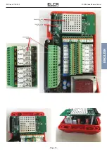
Page 41: ...receiver module IDENTIFICATION CODE CARD It contains as the name suggests the identification code of the system that is unique This code allows the system to recognise the signals transmitted from the transmitter to which it is paired The operating data of the system is also stored on this card EXPANSION CARD Card that allows you to expand your system s functionality so you get eight additional on...

Page 42: ...ENG man E1 MIA 00 E1 MIA Radio Remote Control Page 13 ENGLISH RADIO RECEIVING MODULE IDENTIFICATION CODE CARD EXSPANSION CARD CARD CARD ...

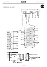
Page 43: ...ENG man E1 MIA 00 E1 MIA Radio Remote Control Page 14 5 2 WIRING EXAMPLE 0Vac SUPPLY 48 55 110 230Vac SUPPLY V 10 55 Vac dc IN1 IN2 IN3 IN4 0V 48V 55V 110V 230V IN1 IN2 IN3 IN4 RIF ...

Page 44: ...l light progressively depending on the charge status of the battery only LED 3 lit indicates that the battery is low LED 1 2 and 3 lit indicate that the battery is fully charged When the battery is fully charged the Charger Check indicator turns green The full charging process lasts about 4 hours The lithium polymer batteries allow a rapid charging process in the initial part of charging The graph...

Page 45: ... illegible please contact an ELCA Service Center to request a duplicate 7 TRANSMITTING UNIT REPLACEMENT To access the card with the unique matching code you must open the door under the battery compartment After rotating the door counterclockwise for about 1 8 turn lift the door making sure not to lose the gasket Below the door is the card with the matching code Raise it gently until it is complet...

Page 46: ...ame time and then it remains awaiting command inputs with the green flashing light flashing slowly 7 3 ENABLING IDENTIFICATION CODE CARD START At the first press of the START key the red and green LEDs light up for 3 seconds Enter the PIN CODE The default PIN CODE is the sequence of START K0 START keys The green LED lights up for 1 second and then turns off Then the Green LED blinking slowly Press...

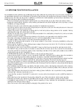
Page 47: ...itters Switch the transmitter off and back on again Green LED fixed and red LED blinks twice every 2 seconds RECEIVER ERROR Switch the transmitter unit off and on again Contact the technical assistance if the problem is not resolved SYSTEM IMPROPERLY INSTALLED Check system for proper installation receiving unit position metal obstacles see Par 2 5 For any causes other than those listed above See P...

Page 48: ...IO CONNECTION FAILURES in Paragraph 8 1 NO RADIO LINK see Paragraph 8 1 RUN THE ENABLE SEQUENCE ON THE TRANSMITTER default start G start AND THEN START DOES THE GREEN LED SWITCH ON WHEN STARTING BLINKING OR FIXED RECHARGE BATTERY see Chapter 6 DOES THE GREEN LED SWITCH ON WHEN STARTING BLINKING OR FIXED IS THE GREEN LED ON FIXED WHEN STARTING IS THE GREEN LED BLINKING AND THE RED LED ON FIXED WHEN...

Page 49: ... SEQUENCE ON THE TRANSMITTER default start G start DOES THE ENABLE LED ON THE RECEIVER FLASH QUICKLY CONTACT SERVICE NO RADIO LINK see Paragraph 8 1 IS RADIO REMOTE CONTROL WORKING CHECK COMPLETED IS RADIO REMOTE CONTROL WORKING PRESS START ON THE ENABLED TRANSMITTER ARE THE 2 LEDs OF THE STOP RELAYS BOTH ON DO THE START AND ACTIVE KEYS LEDs SWITCH ON INCORRECT OPERATION see Paragraph 8 1 CONTACT ...

Page 50: ...REEN LED ON CHARGING CYCLE COMPLETED IS THE RED LED ON CLEAN THE ELECTRICAL CONTACTS ON THE TRANSMITTER AND CHARGING SYSTEM IS THE RED LED ON CHECK THE CHARGING SYSTEM S POWER SUPPLY CONTACT SERVICE IS THE RED LED ON CONTACT SERVICE CHARGING CYCLE COMPLETED WAIT UNTIL CHARGING IS COMPLETE IS THE RED LED OFF AND THE GREEN LED ON HAVE MORE THAN 4 HOURS PASSED YES YES YES YES YES YES NO NO NO NO NO N...

Reviews: