


ITA man E1-MIA 00
Sistema Radiocomando E1-MIA
- Pagina I -
IT
ALIANO
INDICE
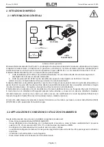
1. MANUALE D’USO
..............................................................................................................................................
1
2. ISTRUZIONI DI IMPIEGO
.................................................................................................................................
2
2.1 INFORMAZIONI GENERALI
............................................................................................................................ 2
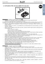
2.2 APPLICAZIONI E CONDIZIONI DI UTILIZZO NON AMMESSI
............................................................ 2
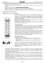
2.3 ISTRUZIONI PER UN USO CORRETTO E SICURO
.............................................................................. 3
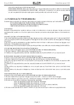
2.4 FUNZIONALITA’ PROGRAMMABILI
............................................................................................................. 5
2.5 INFORMAZIONI PER L’INSTALLAZIONE
................................................................................................... 6
2.6 MANUTENZIONE
................................................................................................................................................ 7
2.7 GARANZIA
............................................................................................................................................................ 8
2.8 INFORMAZIONI SULLO SMALTIMENTO
.................................................................................................... 8
3. DATI TECNICI
......................................................................................................................................................
9
3.1 CARATTERISTICHE GENERALI
................................................................................................................... 9
3.2 CARATTERISTICHE UNITA’ TRASMITTENTE
.......................................................................................... 9
3.3 CARATTERISTICHE UNITA’ RICEVENTE
.................................................................................................. 9
3.4 CARATTERISTICHE SISTEMA DI RICARICA
......................................................................................... 10
4. UNITA’ TRASMITTENTE
................................................................................................................................
10
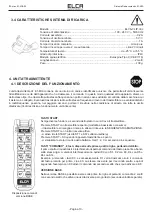
4.1 DESCRIZIONE DEL FUNZIONAMENTO
................................................................................................... 10
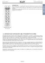
4.2 APPARATI CON SISTEMA MTS (MULTI-TRANSMITTER SYSTEM)
................................................11
5. UNITA’ RICEVENTE
.........................................................................................................................................
12
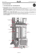
5.1 DESCRIZIONE DEL FUNZIONAMENTO
................................................................................................... 12
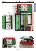
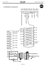
5.2 ESEMPIO DI CABLAGGIO
............................................................................................................................ 14
6. CARICABATTERIE
..........................................................................................................................................
15
6.1 USO DEL CARICABATTERIE
....................................................................................................................... 15
7. SOSTITUZIONE DELL’UNITA’ TRASMITTENTE
...................................................................................
16
7.1 RACCOMANDAZIONI
...................................................................................................................................... 16
7.2 SOSTITUZIONE SCHEDA CODICE DI ABBINAMENTO
...................................................................... 16
7.3 PROCEDURA DI ACQUISIZIONE CODICE IDENTIFICATIVO
........................................................... 17
8. RICERCA GUASTI
...........................................................................................................................................
18
8.1 TIPO DI INCONVENIENTE
............................................................................................................................ 18
8.2 VERIFICA FUNZIONALE APPARATO TRASMITTENTE
...................................................................... 19
8.3 VERIFICA FUNZIONALE UNITA’ RICEVENTE
........................................................................................ 20
8.4 VERIFICA FUNZIONALE DEL CICLO DI CARICA
................................................................................. 21


