0301 / 13 010 881C
30
Service
Maintenance
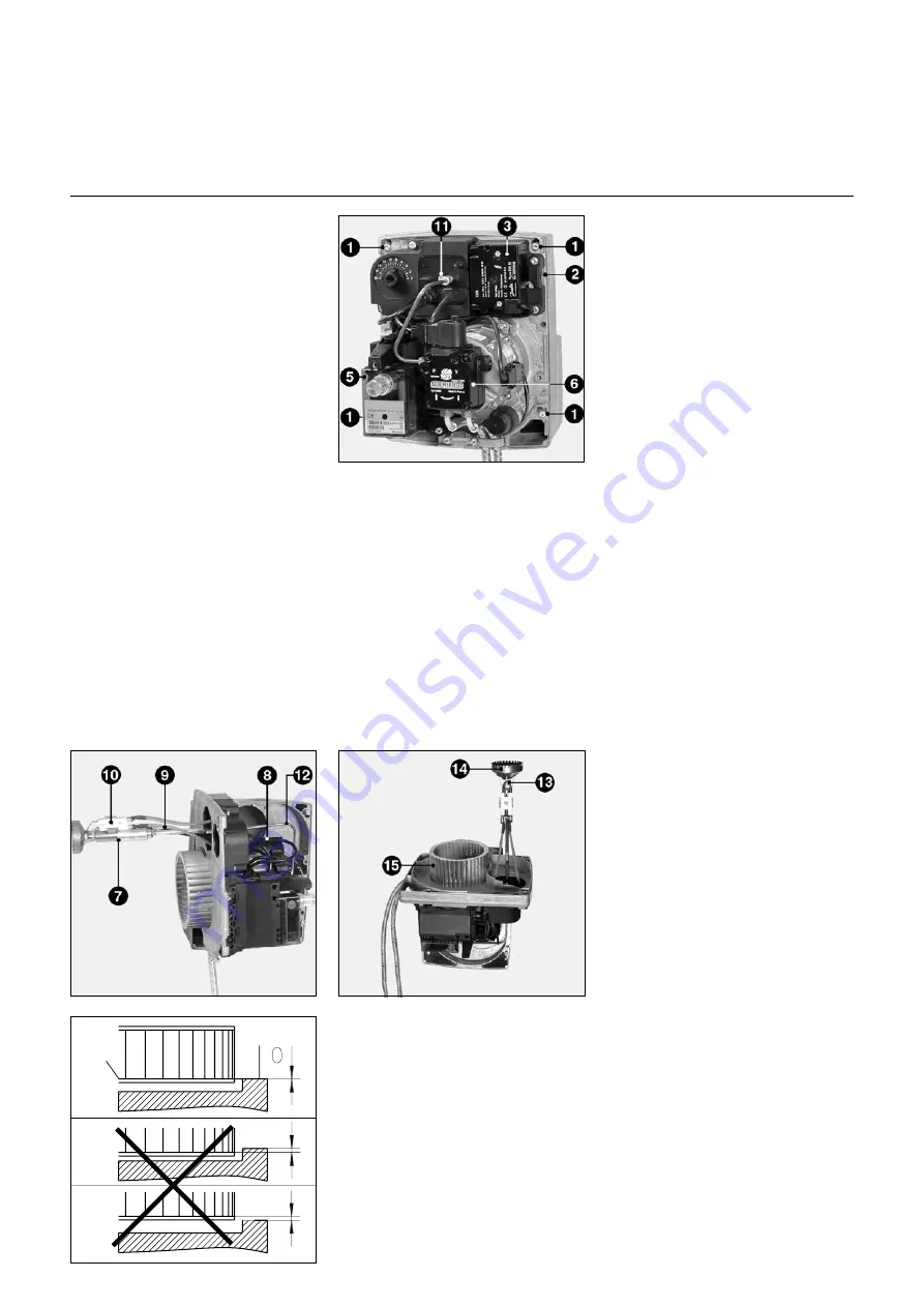
1
Fixing screws
2
Hanger opening
3
Ignition transformer
5
Control and safety unit
6
Oil burner pump
7
Nozzle line
8
Flame monitor
9
Nozzle line el. connection
10
Electrode block
11
Burner head adjusting screw
12
Oil supply connection, Nozzle line
13
Nozzle
14
Turbulator
15
Fan wheel
Fan wheel assembly
Refer to the positions shown in the
diagram on the left when replacing the
motor and fan wheel. The inner flange
A
of the fan wheel must be positioned
level with the device base plate
B
.
Insert a steel rule between the fan
wheel blades and use it to lever points
A
and
B
into alignment. Tighten the
threaded pin on the fan wheel
(maintenance position 2).
A
B
All boiler and burner servicing work
should be carried out by an
appropriately trained heating service
specialist. In order to ensure that the
unit is serviced according to the
maintenance schedule, users are
recommended to enter into a
maintenance contract.
Important
Always shut off the power supply
before carrying out maintenance work
or cleaning tasks.
Checking the exhaust gas
temperature
·
Carry out regular checks to
determine exhaust gas temperature.
·
The boiler must be cleaned whenever
the exhaust gas temperature
exceeds the startup setting by more
than 30K.
·
Fit an exhaust gas temperature
indicator to simplify this checking
procedure.
Maintenance positions
With the screws
1
loosened, the device
base plate can be moved into either of
two maintenance positions.
Position 1
Designed mainly to be used when
replacing the nozzle line.
·
Unscrew oil supply connection
12
·
Unplug unit
9
·
Remove electrode block
10
·
Turn adjusting screw
11
anticlockwise
Position 2
Designed specifically for nozzle and fan
wheel replacement. This position allows
the nozzle to be replaced without
having to drain the nozzle rod.
Burner servicing positions
Position 1
For working, for example, on the pump
Position 2
For working, for example, on the burner
head
Burner maintenance operations
Servicing position 1
·
All oil-bearing components (hoses,
pump, nozzle feed tube) and their
respective couplings should be
checked for tightness and signs of
wear, and replaced as required.
·
Check all electrical connections and
leads for signs of damage, and
replace as required.
·
Check pump filters and clean as
required.
Servicing position 2
·
Clean fan wheel and housing, and
inspect for signs of damage.
·
Inspect and clean the burner head.
·
Dismantle the baffle plate.
·
Replace the oil nozzle.
·
Check ignition electrodes and
readjust or replace as required.
·
Fit burner head. Maintain settings
(see page 28).
·
Fit burner.
·
Start burner, check exhaust-gas data,
correct burner settings as required.
·
Check flame-monitoring device for
correct functioning (see page 29).
Summary of Contents for EK01B.4 L
Page 32: ...0301 13 010 881C 32...
Page 34: ...0301 13 010 881C 34...
Page 42: ...0301 13 010 881C 42 Notizen...
Page 43: ...43 0301 13 010 881C Notizen...


