background image

4

06/2004 - Art. Nr. 13 014 291A

Table of contents

General information
Description

Table of contents

General informations

..................4

Important.......................................4
Description ....................................4

Assembly

.....................................5

Notes

.....................................10-11

Important information

This document is intended to guide
personal qualified in the installation.
Installation and startup must be
performed by a qualified and authorized
technician, in accordance with trade
practices. Both the applicable
regulations and the instructions given in
this manual must be fully complied with.
Any failure - even partial - to observe
these provisions shall absolve the
manufacturer from any liability.

Safety of material and personal

Shut off power supply.
Failure to do so may result in personal
injury or death.

Electrical connection

The set must be wired according to
delivered electrical diagram. Installation
protection and earthing must comply
with applicable regulations.

Modifications made relating to the
installation of this kit must be written in
the burner’s electrical diagram.

Function

The post-ventilation kit enables
ventilation to be continued after the
motor signal coming from the control
and safety unit has been cut off.

Description

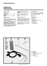
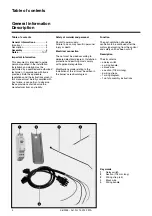
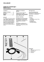
The kit contains:
– a delay switch,
– a wiring bundle,
– a black wire,
– a section (118mm long),
– 5 wiring straps,
– 1 wiring diagram,
– 1 set of assembly instructions.

Key words
1

Delay switch

2

Section (118 mm long)

3

Wiring strap (x5)

4

Black wire

5

Wiring bundle

Summary of Contents for EK03B G

Page 1: ...Montageanleitung Bausatz Nachbel ftung EK03B G EK04B G 2 3 Notice de montage Kit Postventilation EK03B G EK04B G 6 7 Assembly instructions Kit Post ventilation EK03B G EK04B G 4 5 Montage handleiding...

Page 2: ...n Sicherheit des Materials und der Personen Die Stromzufuhr des Brenners abschal ten Zuwiderhandlungen k nnen zu Personen und oder Sachsch den f hren Elektrische Versorgung Der Bausatz mu gem mitgelie...

Page 3: ...er herstellen Das korrekte Funktionieren berpr fen Die Einstellung falls n tig ber bzw auf Skalenscheibe E verfeinern Die Gesamteinstellung berpr fen Brennerhaube montieren Am Sockel des Feuerungsauto...

Page 4: ...y Safety of material and personal Shut off power supply Failure to do so may result in personal injury or death Electrical connection The set must be wired according to delivered electrical diagram In...

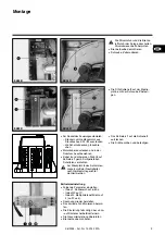
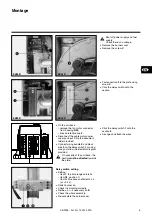
Page 5: ...20 21 10 1 8 4 24 2 11 22 6 5 23 4 25 26 Fasten section 2 to the plate using screw V Click the delay switch onto the section On the unit base remove the fan motor connector from housing 4 24 break pr...

Page 6: ...n de d solidariser le br leur de son alimentation Le non respect de ces consignes peut entra ner des blessures graves voire irr versibles Connexion lectrique Le kit doit tre c bl suivant le document d...

Page 7: ...documentation fournie C bler le faisceau 5 et le fil noir 4 sur le temporisateur 1 selon le sch ma lectrique fourni m Sur l emplacement 6 du socle du coffret le neutre doit tre orient c t platine Enc...

Page 8: ...ructies niet worden nageleefd kunnen ernstige en zelfs onherstelbare letsels worden veroorzaakt Elektrische verbinding De bedrading van de kit moet volgens bijgaand document worden uitgevoerd De zeker...

Page 9: ...het net aansluiten en de zwarte draad 4 op de tijdrelais volgens het bijgeleverde elektrische schema m De nulleider van aansluitklem 6 van de sokkel van de branderautomaat bevindt zich langs de zijde...

Page 10: ...10 06 2004 Art Nr 13 014 291A Notizen Notes Notes Notities...

Page 11: ...11 06 2004 Art Nr 13 014 291A Notizen Notes Notes Notities...

Page 12: ...t in der EU Document non contractuel Non contractual document Angaben ohne Gew hr ELCO Kl ckner A 2544 Leobersdorf ELCO MAT N V S A Researchpark Pontbeeklaan 53 B 1731 Zellik ELCO Kl ckner Heiztechnik...

Reviews: