background image

5

06/2004 - Art. Nr. 13 014 291A

l

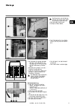
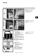
Shut off power supply and fuel
supply.
Check there’s no voltage.

·

Remove the burner cover.

·

Remove the screw

V

.

Montage

Delay switch setting

·

Setting :

– Item

I

: the time range on 6-60s.

– Item

III

: position C.

– Item

II

: time base coefficient on 4

(or

»

22 s).

·

Switch burner on.

·

Check it is working correctly.

·

Refine

+

or

if necessary on

E

.

·

Check the whole assembly.

·

Re-assemble the burner cover.

20

21

10

1/8

4/2

4

2

11

22

6

5

23

-/4

25

26

·

Fasten section

2

to the plate using

screw

V

.

·

Click the delay switch onto the
section.

·

On the unit base :

– remove the fan motor connector

from housing

4/24

,

– break protective cap

6

.

·

Disconnect the cable motor power
supply and put it into the document
folder provided.

·

Connect wiring bundle

5

and black

wire

4

on the delay switch

1

, making

sure you follow the electrical diagram
provided.

m

On socket

6

of the unit base, the

neutral

must be directed

towards

the plate.

·

Click the delay switch

1

onto the

section

2

.

·

Arrange and attach the wires.

EK03B

EK03B

EK04B

EK04B

EN

Summary of Contents for EK03B G

Page 1: ...Montageanleitung Bausatz Nachbel ftung EK03B G EK04B G 2 3 Notice de montage Kit Postventilation EK03B G EK04B G 6 7 Assembly instructions Kit Post ventilation EK03B G EK04B G 4 5 Montage handleiding...

Page 2: ...n Sicherheit des Materials und der Personen Die Stromzufuhr des Brenners abschal ten Zuwiderhandlungen k nnen zu Personen und oder Sachsch den f hren Elektrische Versorgung Der Bausatz mu gem mitgelie...

Page 3: ...er herstellen Das korrekte Funktionieren berpr fen Die Einstellung falls n tig ber bzw auf Skalenscheibe E verfeinern Die Gesamteinstellung berpr fen Brennerhaube montieren Am Sockel des Feuerungsauto...

Page 4: ...y Safety of material and personal Shut off power supply Failure to do so may result in personal injury or death Electrical connection The set must be wired according to delivered electrical diagram In...

Page 5: ...20 21 10 1 8 4 24 2 11 22 6 5 23 4 25 26 Fasten section 2 to the plate using screw V Click the delay switch onto the section On the unit base remove the fan motor connector from housing 4 24 break pr...

Page 6: ...n de d solidariser le br leur de son alimentation Le non respect de ces consignes peut entra ner des blessures graves voire irr versibles Connexion lectrique Le kit doit tre c bl suivant le document d...

Page 7: ...documentation fournie C bler le faisceau 5 et le fil noir 4 sur le temporisateur 1 selon le sch ma lectrique fourni m Sur l emplacement 6 du socle du coffret le neutre doit tre orient c t platine Enc...

Page 8: ...ructies niet worden nageleefd kunnen ernstige en zelfs onherstelbare letsels worden veroorzaakt Elektrische verbinding De bedrading van de kit moet volgens bijgaand document worden uitgevoerd De zeker...

Page 9: ...het net aansluiten en de zwarte draad 4 op de tijdrelais volgens het bijgeleverde elektrische schema m De nulleider van aansluitklem 6 van de sokkel van de branderautomaat bevindt zich langs de zijde...

Page 10: ...10 06 2004 Art Nr 13 014 291A Notizen Notes Notes Notities...

Page 11: ...11 06 2004 Art Nr 13 014 291A Notizen Notes Notes Notities...

Page 12: ...t in der EU Document non contractuel Non contractual document Angaben ohne Gew hr ELCO Kl ckner A 2544 Leobersdorf ELCO MAT N V S A Researchpark Pontbeeklaan 53 B 1731 Zellik ELCO Kl ckner Heiztechnik...

Reviews: