09/2005 - Art. Nr. 13 019 533A
7
Installation
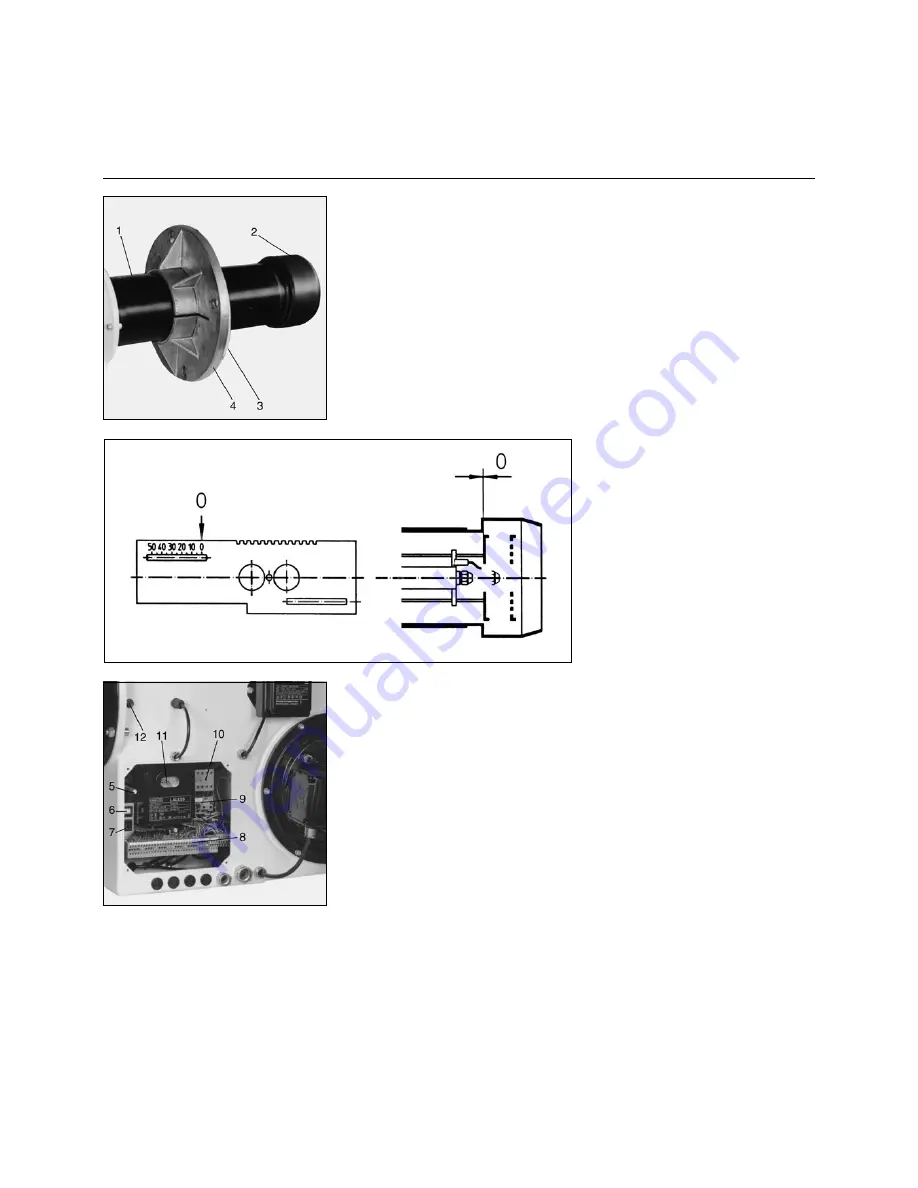
Mounting the burner to the heat generator
Zero point adjustment
Electrical connection
Mounting the burner to the heat
generator
To mount the burner connecting flange
to the heat generator, prepare the con-
necting plate according to the dimen-
sions given on page 4. The connecting
flange
4
with the insulating base
3
have
been factory-mounted to the front of the
burner tube.
·
Set the desired burner tube length in
the furnace by moving the flange on
the burner tube
·
Insert the burner into the opening of
the heat generator and secure it.
Inspection glass cooling
To keep the boiler inspection glass cool
and clean, a cooling line may be
connected to connection
12
R
1/4
”.
The cooling line can be either a hose or
a copper pipe.
A hose union is enclosed with the
burner.
To connect a copper pipe, a suitable
clamping ring connection is required.
Zero point adjustment, flame cup
Before the burner is operated for the
first time, the zero point must be
checked and adjusted, if necessary, so
that the zero mark on the scale corre-
sponds to the zero position in the
burner head. Adjustment is made by
displacing the flame cup after releasing
the screw
1
.
Electrical connection
Electric wiring must be carried out by
an
authorized electrician
according to
the enclosed wiring diagram.
The connecting terminals are located in
the built-in switch box.
For cable connection, ensure the
following:
·
Connect to terminal strip
8
.
·
Provide sufficient length of cable so
that the burner and the boiler door
can be opened.
·
Do
not
install the sensor lead in the
multi-conductor cable.
The electric module can be removed for
connection, replacement or adjustment
of components.
5
Lock nut for electric module
6
Pushbutton, stage 1 - stage 2
7
Pushbutton On/Off
8
El. connecting terminals
9
Overload relay
10 Protective motor switch
11 Automatic burner control unit with
reset button
12 Connection for inspection glass
cooling
Disassembling the electric module
·
Set the main switch to off, remove
the fuse
·
Release the lock nuts
5
·
Carefully remove the electric module.
Caution!
Never apply voltage to the electric
module after disassembly.
After making the connections, check all
system components for correct wiring.
Then start the motor for a short time to
check its sense of rotation.


