09/2005 - Art. Nr. 13 019 533A
9
Start-up
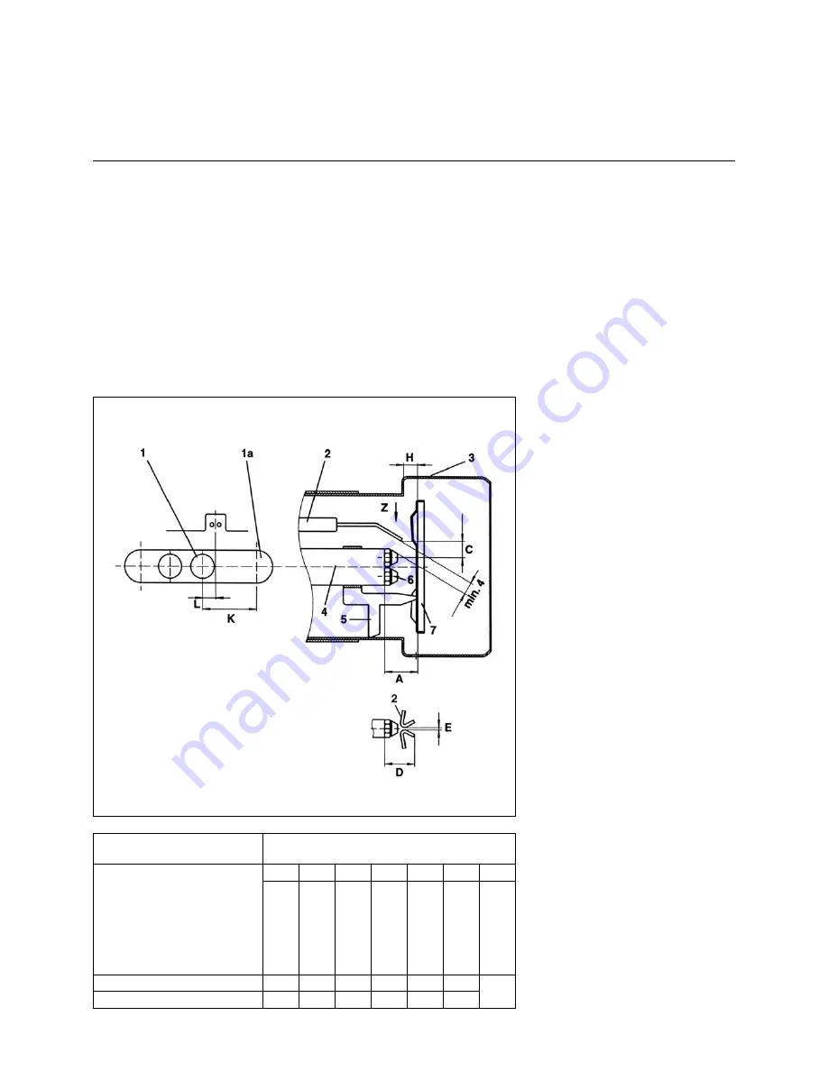
Burner head setting dimensions
The setting dimensions are standard
values which refer to 80% of the
maximum burner capacity. They can be
readjusted depending on operating con-
ditions, flue gas analysis and combu-
stion behaviour.
Important!
Check the settings by means of the
table before starting the burner for the
first time. Remove the nozzle connec-
tion for this purpose.
Ignition electrodes
The ignition electrodes are directed to
nozzle 1.
Spare ignition electrodes must be bent
for replacement (at an angle of approx.
30° to the nozzle).
Burner head
1
Oil connection, minimum low load
1a Oil connection, maximum full load
2
Ignition electrode
3
Flame cup
4
Nozzle rod
5
Baffle plate holder
6
Nozzle
7
Baffle plate
Burner type
Standard settings
A
C
D
E
H
K
L
Baffle
p
late/
nozzle
rod
Electrode/axis
Electrode/
nozzle
rod
Electrode
gap
Baffle
p
late/
flame
c
up
max.
longitudi-
nal
adjustment
Oil
filler
neck/
scale
plate
0
EK 4.100 L-ZA
27
7
20
3
20
50
EK 4.160 L-ZA
27
7
20
3
20
50
View Z


