ELCO S.r.l. - ELK 38 - OPERATING INSTRUCTIONS - Vr. 02 - ISTR 06261 - PAG. 6
In order to obtain good stability of the process variable, in the event
of fast processes, the cycle time “tcr1” has to have a low value with
a very frequent intervention of the control output.
In this case use of a solid state relay (SSR) is recommended for
driving the actuator.
The Single Action PID control algorithm foresees the setting of the
following parameters :
"Pb" – Proportional Band
"tcr1" – Cycle time of the output 1rEG
"Int" – Integral Time
"rS" – Manual Reset (if “Int =0 only)
"dEr" – Derivative Time
“FuOC” - Fuzzy Overshoot Control
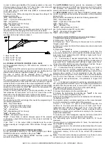
This last parameter allows the variable overshoots at the start up of
the process or at the changing of the Set Point to be avoided.
Please remember that a low value on this parameter reduces the
overshoot while a high value increase it.
1: Value “FuOC” OK
2: Value “FuOC” too high
3: Value “FuOC” too low
4.6 - DOUBLE ACTION PID CONTROL (1rEG - 2rEG)
All the parameters referring to PID control are contained in the
group “
]
rEG”.
The Double Action PID control is used to control plants where there
is an element which causes a positive increase (ex. Heating) and an
element which causes a negative increase (ex. Cooling).
This type of control can be obtained when 2 outputs are
programmed respectively as 1rEG and 2rEG and the par. “Cont” =
Pid.
The element causing a positive increase has to be connected to the
output programmed as 1rEG while the element causing a negative
increase has to be connected to the output programmed as 2rEG.
The Double Action PID control works on the outputs 1rEG and 2rEG
depending on the active Set Point “SP” and on the instrument’s PID
algorithm with two degrees of freedom.
In order to obtain good stability of the process variable, in case of
fast processes, the cycle times “tcr1” and “tcr2” have to have a low
value with a very frequent intervention of the control outputs.
In this case use of solid state relays (SSR) to drive the actuators is
recommended.
The Double Action PID control algorithm needs the programming of
the following parameters :
"Pb" – Proportional Band
"tcr1" – Cycle time of the output 1rEG
“tcr 2” – Cycle time of the output 2rEG
"Int" – Integral Time
"rS" – Manual Reset (if “Int =0 only)
"dEr" – Derivative Time
“FuOC” - Fuzzy Overshoot Control
"Prat" - Power Ratio or relation between power of the element
controlled by output 2rEG and power of the element controlled by
output 1rEG.
If par. “Prat” = 0, the output 2rEG is disabled and the control
behaves exactly as a single action PID controller, through output
1rEG.
4.7 - AUTOTUNING AND SELFTUNING FUNCTIONS
All the parameters referring to the AUTO-TUNING and SELF-
TUNING functions are contained in the group “
]
rEG”.
The AUTO-TUNING and SELF-TUNING functions permit the
automatic tuning of the PID controller.
The AUTO-TUNING function permits the calculation of thePID
parameters by means of a FAST type tuning cycle and, at the end of
this operation, the parameters are stored into the instrument’s
memory and remain constant during control.
The SELF-TUNING function (rule based "TUNE-IN") instead allows
control monitoring and the continuous calculation of the parameters
during control.
Both functions automatically calculate the following parameters :
"Pb" – Proportional Band
"tcr1" – Cycle time of the output 1rEG
"Int" – Integral Time
"dEr" – Derivative Time
“FuOC” - Fuzzy Overshoot Control
and, for the Double Action PID control, also :
“tcr 2” – Cycle time of the output 2rEG
"Prat" - Ratio P 2rEG/ P 1rEG
To activate the AUTO-TUNING function proceed as follows :
1) Program and activate the desired Set Point.
2) Program par. "Cont" =Pid.
3) Program par. "Func" according to the process to be controlled
through output 1rEG.
4) Program an output as 2rEG if the instrument controls a plant with
double action
5) Program par. "Auto" as:
- "1” – if auto-tuning is desired automatically, each time the
instrument is switched on, on the condition that the process value is
lower (with “Func” =HEAt) than [SP- |SP/2|] or higher (with “Func”
=CooL) than [SP+ |SP/2|].
- "2" – if auto-tuning is desired automatically, the next time the
instrument is switched on, on the condition that the process value is
lower (with “Func” =HEAt) than [SP- |SP/2|] or higher (with “Func”
=CooL) than [SP+ |SP/2|], and once the tuning is finished, the par.
“Auto” is automatically swapped to the OFF state
- "3" - if manual auto-tuning is desired, by selecting par. “tunE” in
the main menu or by correctly programming key “U” as “USrb” =
tunE. In this case the auto-tuning starts without any control on the
process value condition. It is recommended to use this option,
starting the auto-tuning when the process value is as far as possible
from the Set Point because, in order to feature the Auto-tuning
FAST with its best performances , it is preferable to respect this
condition.
- "4" - if it’s desired to activate the autotuning automatically at the
end of programmed Soft-Start cycle. The Autotuning will start at the
condition that the process value is lower (with “Func” =HEAt) than
[SP- |SP/2|] or higher (with “Func” =CooL) than [SP+ |SP/2|].
6) Exit from the parameter programming.
7) Connect the instrument to the controlled plant.
8) Activate the Auto-tuning by selecting par. “tunE” in the main
menu (or by correctly programming key “U” ).
At this point the Auto-tuning function is activated and is indicated by
the flashing led AT/ST.
The regulator carries out several operations on the connected plant
in order to calculate the most suitable PID parameters.
If “Auto” = 1 or “Auto” = 2, and if, at the Auto-tuning start, the
condition for the lower process value is not found (with “Func”
=HEAt) than [SP- |SP/2|] or higher (with “Func” =CooL) than [SP+
|SP/2|], the display will show “ErAt” and the instrument will be
swapped to normal control conditions according to the previously
programmed parameters.
To make the error “ErAt” disappear, swap the instrument to the OFF
control (OFF) and then turn it to automatic control (rEG).
The Auto-tuning cycle duration has been limited to 12 hours
maximum.
If Auto-tuning is not completed within 12 hours, the instrument will
show "noAt" on the display.
In case of probe error, the instrument automatically stops the cycle
in progress.
The values calculated by Auto-tuning are automatically stored in the
instrument’s memory at the end of the correct PID parameters
tuning.
Note : The instrument is already programmed in our factory to carry
out auto-tuning at every instrument switch on ("Auto" = 1).


